
Mobile railway track defect detection

a technology for railway tracks and defects, applied in the direction of instruments, structural/machine measurement, and processing detected response signals, etc., can solve problems such as deterioration of service, faults that can occur, and endanger human lives

Pending Publication Date: 2020-08-27
BOARD OF RGT THE UNIV OF TEXAS SYST
View PDF2 Cites 3 Cited by
  • Summary
  • Abstract
  • Description
  • Claims
  • Application Information

AI Technical Summary

Benefits of technology

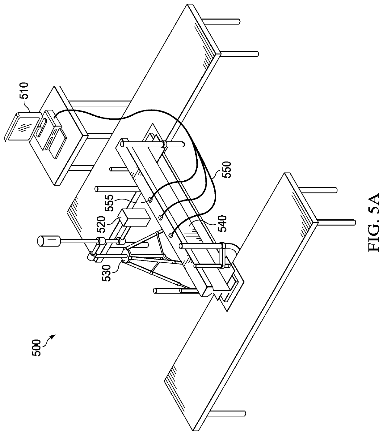
The patent describes a system and method for detecting defects in railway tracks using a mobile platform with an excitation mechanism and a laser Doppler vibrometer. The system applies multiple impact forces to the railway track and captures vibration data through the use of a laser Doppler vibrometer. The vibration data is then analyzed using a modal parameter analyzer to detect any defects in the railway track. The system can also measure the vibration of the laser Doppler vibrometer while the mobile platform travels along the railway track using an accelerometer. The technical effect of this patent is to provide a reliable and efficient means for detecting defects in railway tracks.

Problems solved by technology

Faulty railway tracks can endanger human lives and deteriorate service.
One of the most significant types of faults that can occur is an internal crack located in a track head.
These types of cracks can be caused by inherent manufacturing processes, cyclic loading, impact from rolling stock, rail flow, and wheel contact stress, for example.
However, current ultrasonic damage detection methods for railway tracks are likely to be insufficient to detect internal cracks in a railway track head.
Any artificial crack, however small, located on the surface close to a critical internal crack can affect the reflection of ultrasound waves.
However, the detection of internal cracks in track heads using vibration based damage detection methods has not been addressed.

Method used


Image

  • Mobile railway track defect detection
  • Mobile railway track defect detection
  • Mobile railway track defect detection

Examples


Embodiment Construction

)

[0046]In the following description, details are set forth by way of example to facilitate discussion of the disclosed subject matter. It should be apparent to a person of ordinary skill in the field, however, that the disclosed embodiments are exemplary and not exhaustive of all possible embodiments. For a more complete understanding of the present disclosure, reference is made to the following description and accompanying drawings.

[0047]As noted above, current ultrasonic damage detection methods for railway tracks are likely to be insufficient to detect internal cracks in a railway track head. For example, when an artificial crack is located above a critical internal crack, the artificial crack can prevent the ultrasonic waves from reaching the critical internal crack. As described in detail herein, vibration measurements recorded from the surface of railway tracks, rather than ultrasonic measurements, may be used to detect internal cracks in railway tracks. The quality of these m...


PUM


Abstract

A railway track defect detection system may include a mobile defect detection platform and a modal parameter analyzer. The platform may include an excitation mechanism (e.g., an excitation hammer or wheels that are in contact with a railway track) to apply multiple impact forces to the railway track while the platform travels along the railway track, and a laser Doppler vibrometer to capture, while the platform travels along the railway track, vibration data representing vibrations of the railway track caused by application of the multiple impact forces by the excitation mechanism. The modal parameter analyzer may be configured to detect, based on the vibration data captured by the laser Doppler vibrometer, a defect in the railway track. For example, changes in vibration amplitudes, mode shapes, damping ratios, or a natural frequency derived from the received vibration data may indicate the presence of a defect in the railway track.

Description

[0001]This application claims priority to U.S. Provisional Application No. 62 / 559,726 filed Sep. 18, 2017, entitled “Mobile Railway Track Defect Detection,” which is incorporated herein by reference in its entirety.FIELD OF THE DISCLOSURE[0002]The present disclosure relates generally to systems and methods for detecting defects in railway tracks and, more specifically, to detecting internal cracks in railway tracks using moving laser sensors.DESCRIPTION OF THE RELATED ART[0003]The benefits of railway transportation for improving economies and urban development is understood by many countries. Railway transportation plays a key role in the mass transportation of products and passengers. Consequently, human lives and the economies of many countries strongly depend on the availability of safe and efficient railway transportation. For this reason, government transportation agencies and railway companies put significant effort into systems and methods to ensure safety and the uninterrupt...

Claims


Application Information

Patent Timeline
IPC IPC(8): G01M5/00G01N29/04G01N29/24G01N29/44
CPCG01N2291/2623G01M5/0025G01M5/0066G01N29/2418G01N29/045G01N29/4445G01M5/0075G01N29/42G01H9/00G01M7/08G01N29/46G01M17/03
Inventor KAYNARDAG, KORKUTSALAMONE, SALVATORE
Owner BOARD OF RGT THE UNIV OF TEXAS SYST
Learn More