
Method and apparatus for reconstructing a point cloud representing a 3D object

a point cloud and object technology, applied in the field of point cloud reconstruction, can solve the problems of typical static and huge point clouds, and achieve the effect of improving the visual quality of reconstructed point clouds

Active Publication Date: 2020-08-13
INTERDIGITAL VC HLDG INC
View PDF4 Cites 10 Cited by
  • Summary
  • Abstract
  • Description
  • Claims
  • Application Information

AI Technical Summary

Benefits of technology

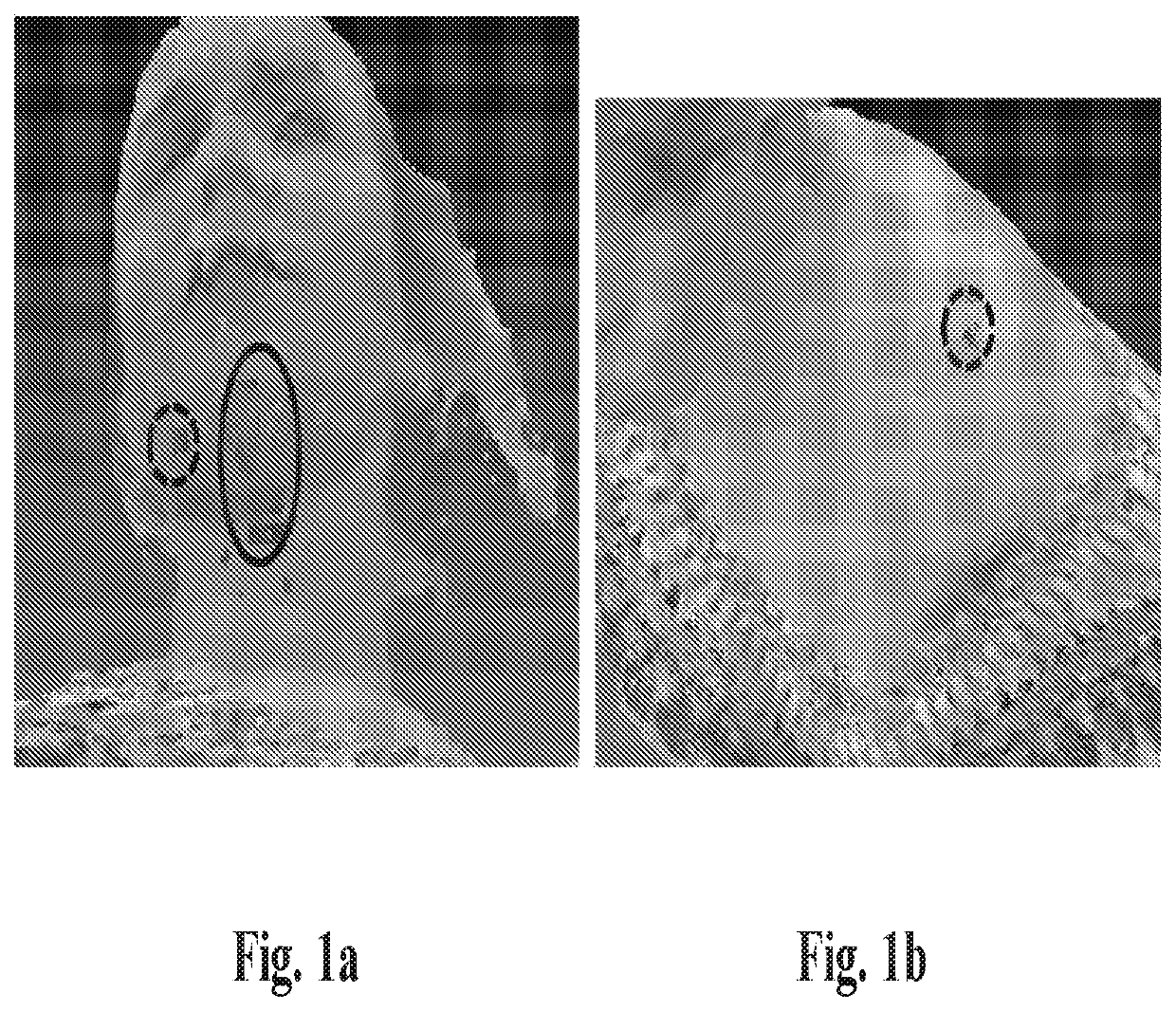
The invention aims to improve the quality of reconstructed point clouds generated by a point cloud codec based on projections and octrees. It does this by completing the missing parts while minimizing the number of new points added to the reconstructed point clouds without introducing high computational complexity. By using a structure of projection, the volume positions can be captured finely to capture occlusions. Additionally, the invention includes a step of detecting the missing part in the inverse-projected point cloud and removing false boundary points to improve the visual quality of the reconstructed point cloud.

Problems solved by technology

Such colored point clouds are typically static and huge.

Method used


Image

  • Method and apparatus for reconstructing a point cloud representing a 3D object
  • Method and apparatus for reconstructing a point cloud representing a 3D object
  • Method and apparatus for reconstructing a point cloud representing a 3D object

Examples


first embodiment

[0245]FIG. 9 is a diagram of sub-steps of the step 880 according to a

[0246]In a step 900, at least one missing part MP1 in the inverse-projected point cloud IPPC is detected.

[0247]In step 910, each missing part MPq is completed based on points in the neighborhood of said at least one missing part in order to generate a completed inverse-projected point cloud IPPC′.

[0248]In step 920, the completed inverse-projected point cloud IPPC′ and the octree-based structure GO are fused to generate the reconstructed point cloud RPC.

[0249]In step 900, the missing parts MPq are detected by first detecting boundary points of these missing parts. This requires analyzing the neighborhood of each point of IPPC,

[0250]The distance-S neighbors of a point P is defined as the neighboring points falling on a sphere or a cube whose center is P and with sphere diameter or cube scale equal to 2*S. The distance-S neighborhood of a point P(xP, yP, zP) is defined by

{Neigh(xNeigh, yNeigh, zNeigh), |xNeigh−xP|=S &...

second embodiment

[0311]The distance-1 neighborhood of each point of RPC can be completed according to a

[0312]In this second embodiment, instead of checking the distance-1 neighborhood of each existing point (first embodiment), the distance-1 neighborhood of each non-occupied position is checked. Denote each non-occupied occupied position as PUnOccup(xUnOccup, yUnOccup, zUnOccup).

[0313]For each PUnOccup, check the number of its distance 1 neighbors in the current point cloud, which is denoted as KPUnOccup1. If KPUnOccup1 is within a reasonable range, in the other words, less than the usual value of KP1 when the distance 1 neighborhood of P is complete and greater than a lower bound, PUnOccup is possible to be a new point and be added to the point cloud. In this case, PUnOccup is further checked. That is to say, if TUnOccup1aPUnOccup1UnOccup1b, PUnOccup is further checked. Otherwise, PUnOccup is not further checked. The possible values are TUnOccup1a=13 and TUnOccup1b=5.

[0314]If PUnOccup is further ch...


PUM


Abstract

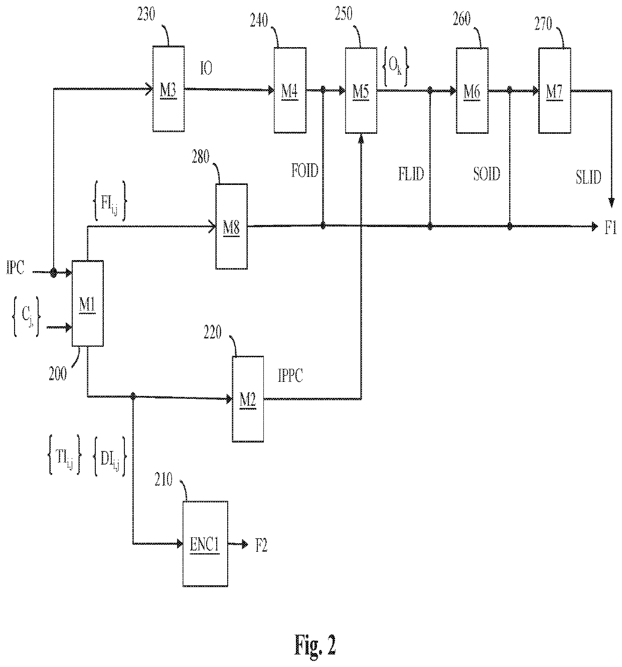
The present disclosure concerns a method for reconstructing a point cloud representing a 3D object from an inverse projected point cloud (IPPC) obtained by inverse-projecting at least one depth image of an original point cloud, said at least one depth image being obtained by projecting the points of the original point cloud onto at least one surface, said method comprising the steps of; detecting (900) at least one missing part (MPtfj in the inverse-projected point cloud (IPPC), and completing (910) said at least one missing part (MPq) based on points in the neighborhood of said at least one missing part.

Description

TECHNICAL FIELD OF THE INVENTION[0001]The present principles generally relate to the reconstruction of a point cloud representing a 3D object from an inverse-projected point cloud (IPPC) and eventually a point cloud associated to an octree based structure, Particularly, but not exclusively, the technical field of the present principles are related to the reconstruction of point cloud that uses a texture and depth projection scheme.BACKGROUND OF THE INVENTION[0002]The present section is intended to introduce the reader to various aspects of art, which may be related to various aspects of the present principles that are described and / or claimed below. This discussion is believed to be helpful in providing the reader with background information to facilitate a better understanding of the various aspects of the present principles. Accordingly, it should be understood that these statements are to be read in this light, and not as admissions of prior art.[0003]A point cloud is a set of po...

Claims


Application Information

Patent Timeline
IPC IPC(8): G06T5/00G06T9/40G06T19/00
CPCG06T19/00G06T2210/56G06T5/005G06T9/40G06T9/001G06T5/77
Inventor CAI, KANGYINGRICHARD, JULIENGUEDE, CELINE
Owner INTERDIGITAL VC HLDG INC
Learn More