
Blow mould

a blow mould and mould body technology, applied in the field of blow moulds, can solve the problems of inflexible pattern design, time-consuming and laborious, and the pattern can only be applied by milling, and achieve the effect of sufficient resistan

Active Publication Date: 2020-08-06
RESILUX NV
View PDF3 Cites 2 Cited by
  • Summary
  • Abstract
  • Description
  • Claims
  • Application Information

AI Technical Summary

Benefits of technology

The invention describes a thin insert that can be used to create products using blow molding with embossing. The insert is made from a strong material that can withstand high pressure, and it is economical to produce. The insert can be easily inserted into a blow mold and can create products with a maximum depth of embossing of 2.0 mm. Overall, this invention allows for the creation of products with unique embossing patterns using a simple and cost-effective process.

Problems solved by technology

As a result, a pattern can only be applied by milling.
In order to obtain the desired detailing, this is a time-consuming manner.
This results in a very expensive solution that is not flexible to change pattern design.
However, the major disadvantage is that the detailing in transferring the embossing via the stamp is quite poor.

Method used


Image

  • Blow mould
  • Blow mould

Examples


Embodiment Construction

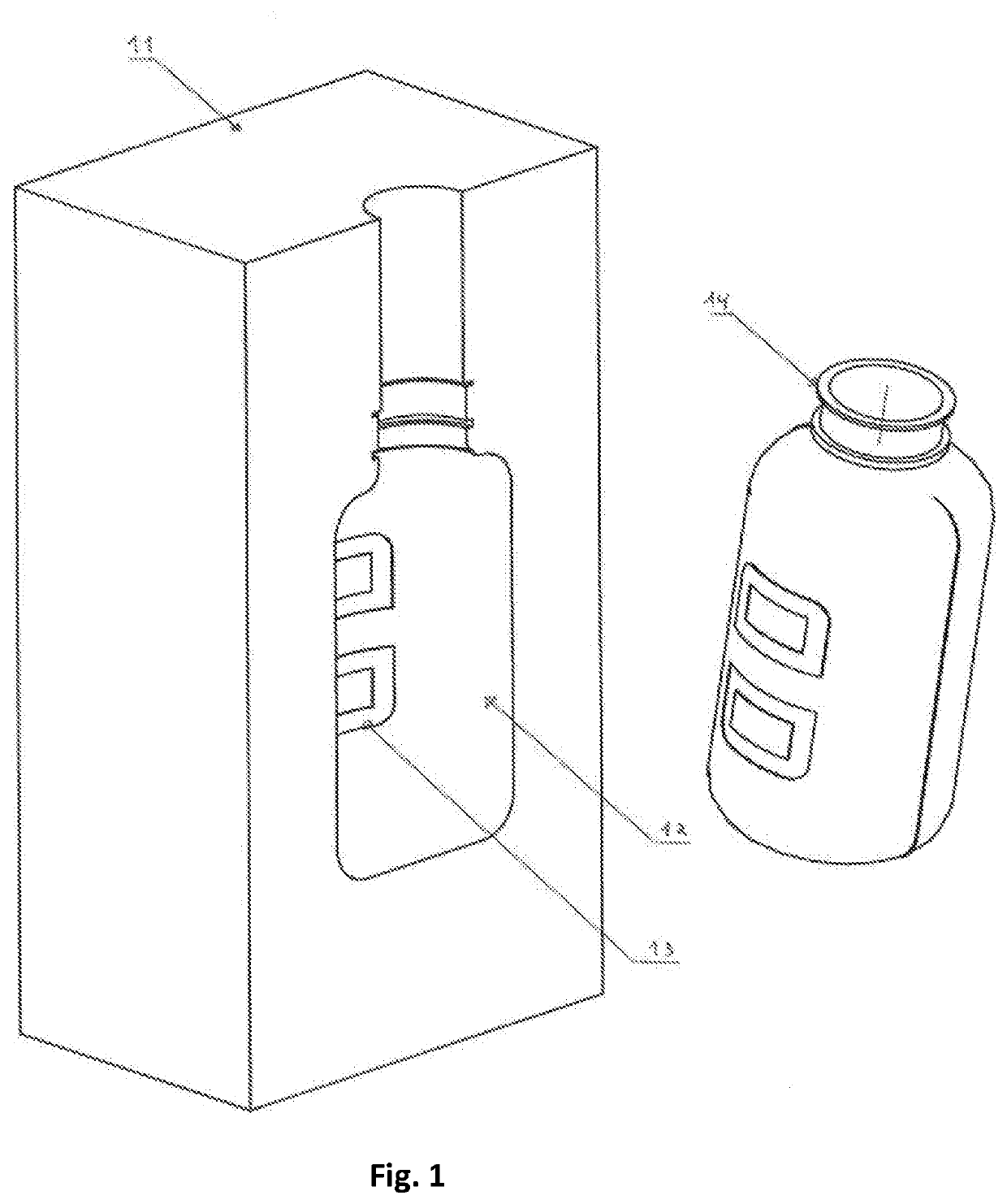
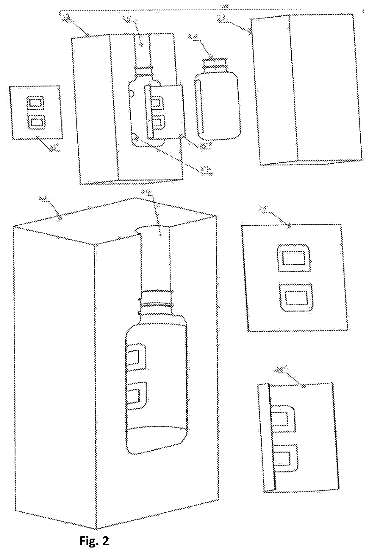
[0012]The present invention aims to offer a solution to the aforementioned requirements. The present invention provides a blow mould comprising at least a first and a second blow mould element provided to inscribe a concavity, at least one insert having an embossed surface provided to form a pattern onto a blow-moulded surface, where the aforementioned at least one insert is attached onto a surface of at least one of the aforementioned first and / or the aforementioned second blow mould element and provided to form a part of a wall of the blow-moulded product. According to the invention, such blow mould is such that the aforementioned at least one insert is a plate having a wall thickness of between 0.2 mm and 2.0 mm, where the aforementioned at least one insert is attached onto at least one of the aforementioned first and / or the aforementioned second blow mould element by reversible fixation means selected from the group consisting of adhesives, preferably a double-sided adhesive tap...


PUM

PropertyMeasurementUnit
Thicknessaaaaaaaaaa
Thicknessaaaaaaaaaa
Thicknessaaaaaaaaaa

Abstract

A blow mould includes at least first and second blow mould elements that inscribe a concavity; and at least one insert having an embossed surface to form a pattern onto a blow-moulded surface. The at least one insert is attached onto a surface of at least one of the first and / or second blow mould elements to form a part of the wall of the blow-moulded product. Such blow mould is an ISBM blow mould and the blow mould is such that the at least one insert is a plate having a wall thickness of between 0.2 mm and 2.0 mm and is attached onto at least one of the first and / or second blow mould elements by a reversible fixation mechanism selected from the group of adhesives, preferably a double-sided adhesive tape, a magnet and a geometric mechanism.

Description

SCOPE OF THE TECHNOLOGY[0001]The present invention relates to a blow mould, a method for producing the blow mould and the use of the blow mould in blow processes such as injection stretch blow moulding (ISBM), injection blow moulding (IBM) or extrusion blow moulding (EBM) and for all products from all plastics that may be blown using these techniques, such as polyesters (PET, PETG, etc.) and polyolephines (PP, PE, etc.) blow-moulded products.STATE OF THE ART[0002]It is generally known that various ways already exist to provide products produced by a blow process with a pattern through embossing. The known solutions can largely be divided into two groups. In a first group, the desired pattern is applied to the wall of a blow mould. During blowing, the bottle will adopt this shape. This method has two major disadvantages. On the one hand, a different blow mould needs to be constructed for each change in the pattern design. On the other hand, the pattern design also needs to be applied...

Claims


Application Information

Patent Timeline
IPC IPC(8): B29C49/52B29C49/06B29C33/42B29C33/38
CPCB29C33/424B29C49/52B29C49/06B29C33/3842B29C33/306B29C49/48B29C2049/4858B29C2049/4874B29C49/487105B29C2049/023
Inventor DE CUYPER, DIRKDIERICKX, WILLIAMANTHIERENS, TOM
Owner RESILUX NV
Learn More