
System For Charging Wireless Devices

a wireless device and wireless charging technology, applied in the direction of charging attachments/accumulators, emergency power supply arrangements, transportation and packaging, etc., can solve the problems of energy to be dispersed, become more prone to corrosion, and sensors can consume significant amounts of energy

Active Publication Date: 2020-07-02
GOOGLE LLC
View PDF0 Cites 16 Cited by
  • Summary
  • Abstract
  • Description
  • Claims
  • Application Information

AI Technical Summary

Benefits of technology

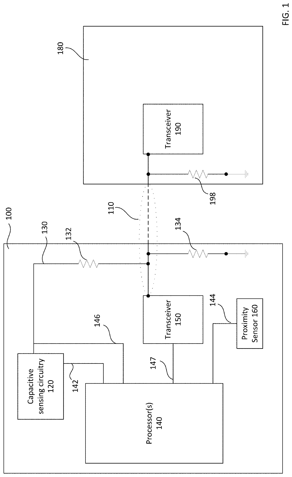
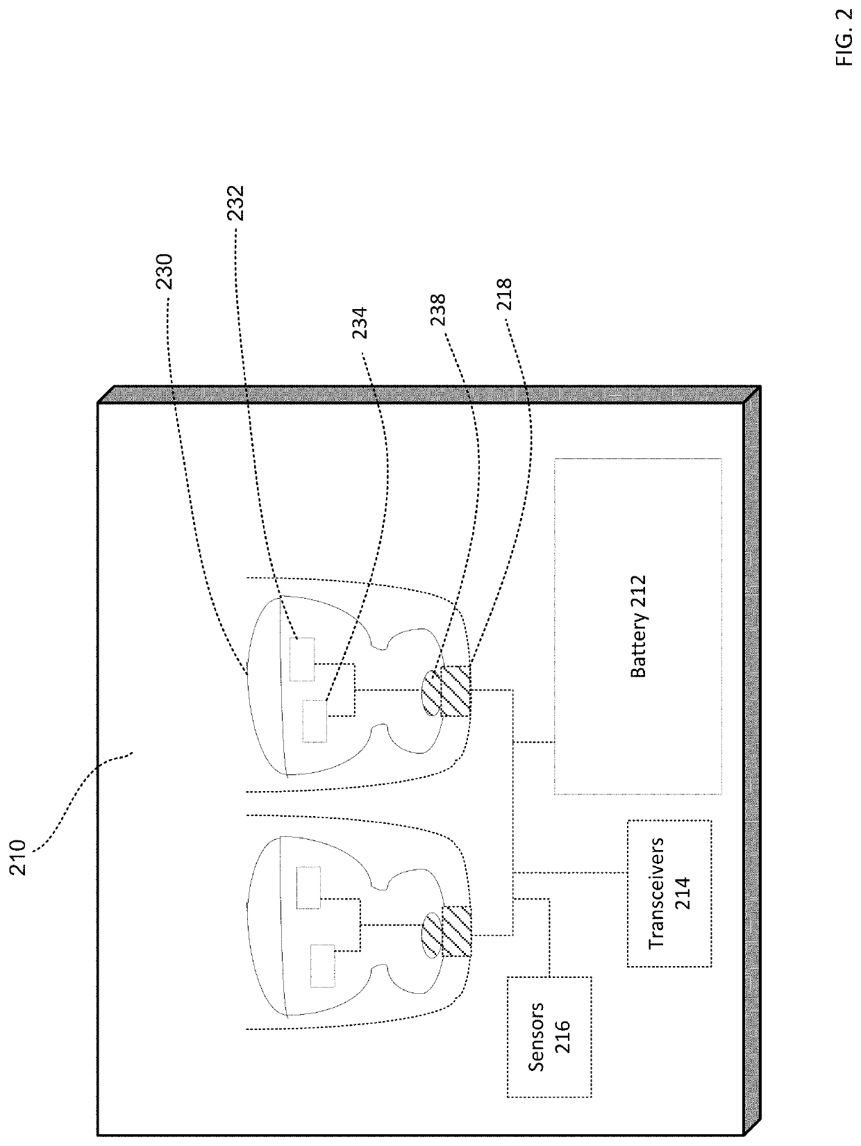
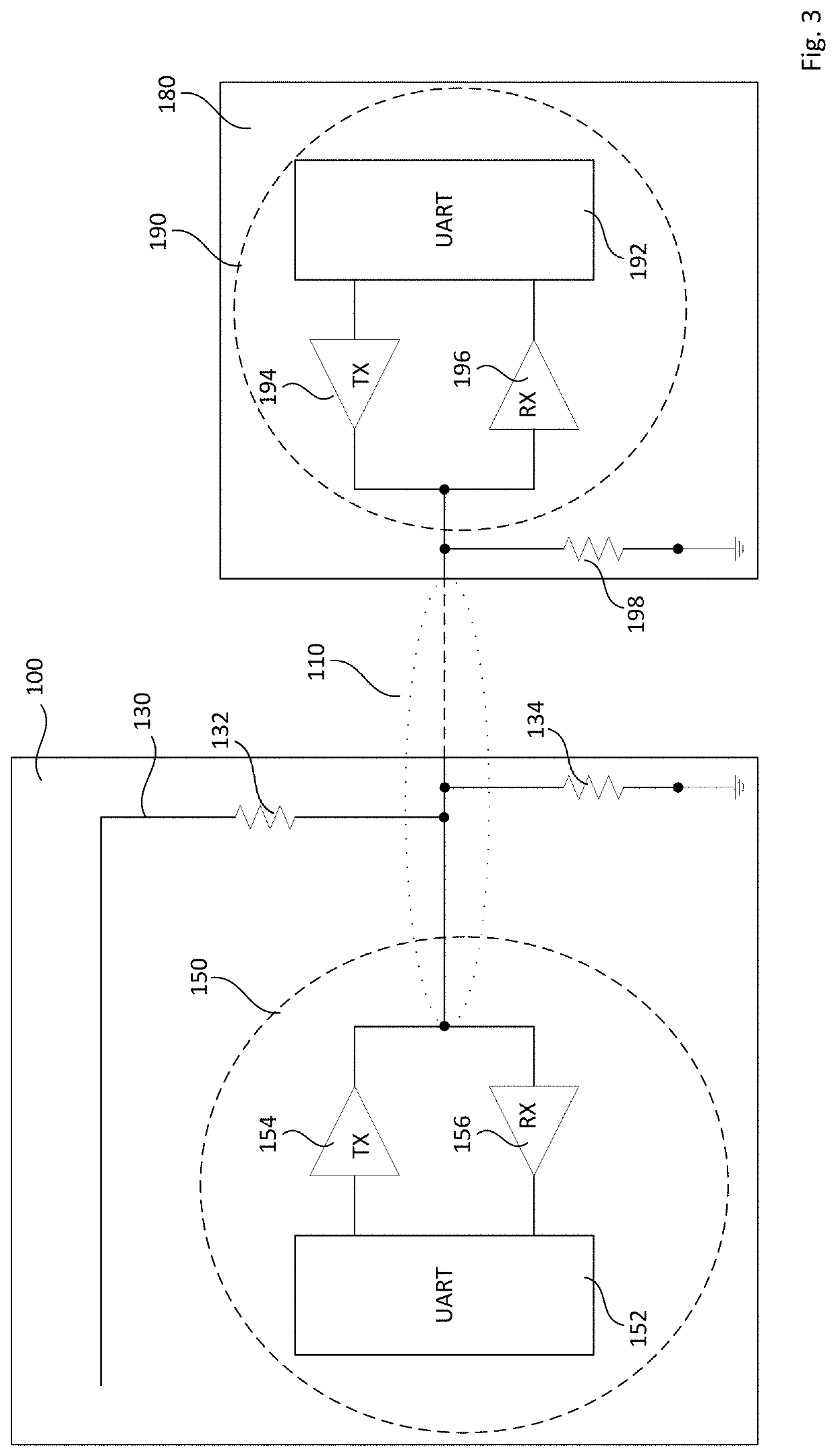
The present patent provides a case for charging wireless devices that includes capacitive sensing circuitry for detecting if the wireless devices are inside the case. The case also includes a transceiver for transmitting and receiving data to and from the wireless devices. The case can detect if the wireless devices are positioned inside the case and activate the transceiver to connect the wireless devices to the case. The case can also set a sampling rate for the capacitive sensing circuitry based on whether the wireless devices are positioned inside the case or not. The case can also include a pull-up resistor and a pull-down resistor to control the charging of the wireless devices. The system also includes a second capacitive sensing circuitry and a second transceiver for wireless devices that are positioned inside the case. The technical effects of this patent include improved charging efficiency and convenience for users who need to charge their wireless devices while on-the-go.

Problems solved by technology

However, such electrical components, when kept active for extended periods of time, may cause energy to be dissipated and become more prone to corrosion.
Such sensors can also consume significant amounts of energy when kept active for extended periods of time.

Method used


Image

  • System For Charging Wireless Devices
  • System For Charging Wireless Devices
  • System For Charging Wireless Devices

Examples


Embodiment Construction

Overview

[0025]The technology generally relates to a case for housing and charging one or more wireless devices, such as wireless earbuds. The case includes capacitive sensing circuitry for detecting whether the wireless devices are positioned inside the case based on a capacitance of the wireless devices. The case also includes a transceiver for transmitting data to and receiving data from the wireless devices. When the wireless devices are positioned inside the case, an electrical component inside the case operatively connects the capacitive sensing circuitry and the transceiver of the case to the wireless devices. The case further includes one or more processors for controlling the capacitive sensing circuitry, the transceiver, and the electrical component. For example, the one or more processors may be configured to control a sampling rate of the capacitive sensing circuitry, a communication rate of the transceiver, and / or charging of the wireless devices.

[0026]The capacitive sen...


PUM


Abstract

A case (100) is provided for housing and charging one or more wireless devices (180), such as wireless earbuds. The case (100) includes capacitive sensing circuitry (120) for detecting whether the wireless devices (180) are positioned inside the case (100) based on a capacitance of the wireless devices (180). The case (100) also includes a transceiver (150) for transmitting data to and receiving data from the wireless devices (180). When the wireless devices (180) are positioned inside the case (100), an electrical component (110) inside the case operatively connects the capacitive sensing circuitry (120) and the transceiver (150) of the case (100) to the wireless devices (180). The case (100) further includes one or more processors (140) for controlling the capacitive sensing circuitry (120), the transceiver (150), and the electrical component (110).

Description

BACKGROUND[0001]Wireless devices typically require one or more batteries, such as a rechargeable battery, that provides power to the wireless device. Such rechargeable batteries need to be periodically recharged or replaced. Cases for housing wireless devices can be configured to charge the batteries of the wireless devices and to communicate with the wireless devices. As such, electrical components like wires and contacts are often needed for enabling communication and charging. However, such electrical components, when kept active for extended periods of time, may cause energy to be dissipated and become more prone to corrosion.[0002]Electrical and mechanical sensors can be used to detect conditions of the cases and the wireless devices. Such sensors can also consume significant amounts of energy when kept active for extended periods of time.BRIEF SUMMARY[0003]The present disclosure provides for a case configured for charging one or more wireless devices, the case comprising capac...

Claims


Application Information

Patent Timeline
Patent Type & Authority Applications(United States)
IPC IPC(8): H04R1/10H02J50/90H02J50/00H02J7/00
CPCH02J50/90H04R1/1025H02J50/005H02J2310/22H04R1/1016H02J7/0045H02J7/0036H02J7/0044H02J9/005H04R2460/17A45C15/00A45C2011/002H02J7/00038H02J7/00034H02J7/342H02J7/0013
Inventor DING, YAOALBANOWSKI, KENNETHSHMUKLER, MAKSIMHERMOSILLO, TREVORLEUNG, CHI KIN BENJAMIN
Owner GOOGLE LLC
Learn More