
Valve timing in electronically commutated hydraulic machine

Pending Publication Date: 2020-07-02
ARTEMIS INTELLIGENT POWER
View PDF18 Cites 1 Cited by
  • Summary
  • Abstract
  • Description
  • Claims
  • Application Information

AI Technical Summary

Benefits of technology

The patent text discusses a way to improve the reliability and smooth operation of a fluid working machine by reducing the risk of cycle failures caused by temporary accelerations. These accelerations can occur when there is a transient decrease in torque, such as when gears in a drivetrain backlash. The patent proposes using an alternative phase to control the opening or closing of valves, which can help to advance or retard the target phase of the valves and dampen oscillations in the drivetrain that may be associated with temporary accelerations. This method improves the reliability and smoothness of the fluid working machine.

Problems solved by technology

We have found that these temporary accelerations can be a particular cause of cycle failure.
They typically arise due to a temporary change in torque, for example a transient decrease in torque due to backlash between gears in a drivetrain driven by the fluid working machine.
We have also found that temporary changes in the pressure in the high pressure manifold can cause cycle failure, by changing the precise phase at which valves open or close, particularly the phase of opening or closing the high pressure valve.

Method used


Image

  • Valve timing in electronically commutated hydraulic machine
  • Valve timing in electronically commutated hydraulic machine
  • Valve timing in electronically commutated hydraulic machine

Examples


Embodiment Construction

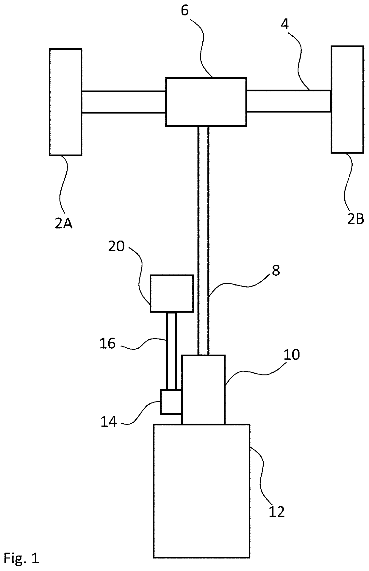
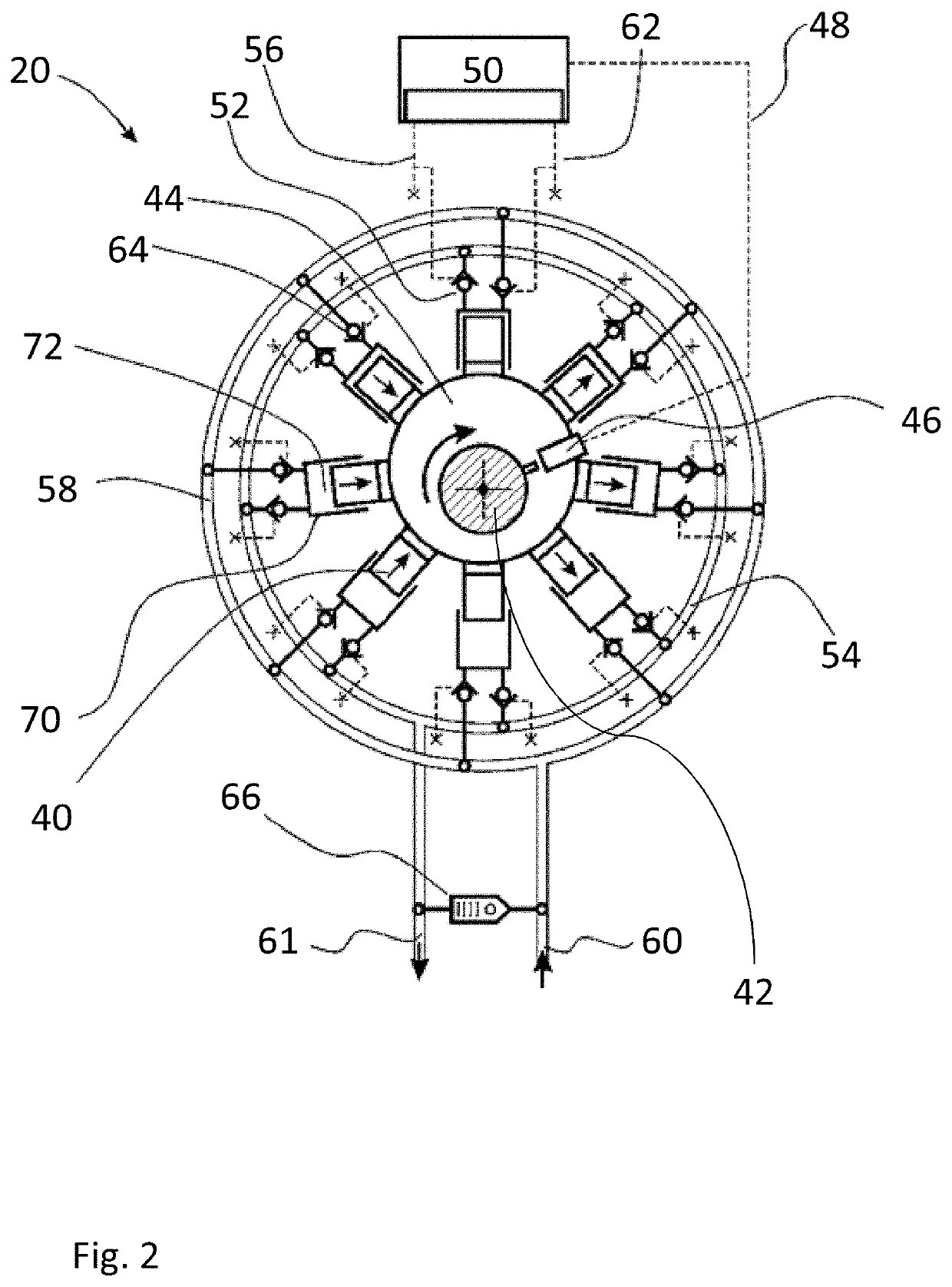
[0087]FIG. 1 illustrates a vehicle drivetrain within which the invention can be employed. The drivetrain has a first wheel 2A and a second wheel 2B, an axle 4, a rear differential 6, a driveshaft 8, a gearbox 10, an internal combustion engine (ICE) 12, a power take off (PTO) 14, an intermediate shaft 16 and an electronically commutated hydraulic machine (ECM) 20. The intermediate shaft and gearbox are configured to transfer torque to one another via the PTO. The PTO is mechanically connected to the gearbox and typically contains at least two gears including a first gear in rotatable torque communication with a gear of the gearbox and a second gear which is non-rotatably secured to the intermediate shaft. The ICE functions as the prime mover, optionally driving the ECM and thereby the wheels, through the intervening drivetrain. The ECM may also be driven, for example, when carrying out regenerative braking.

[0088]As well as vehicles, the invention is useful in many other types of mach...


PUM


Abstract

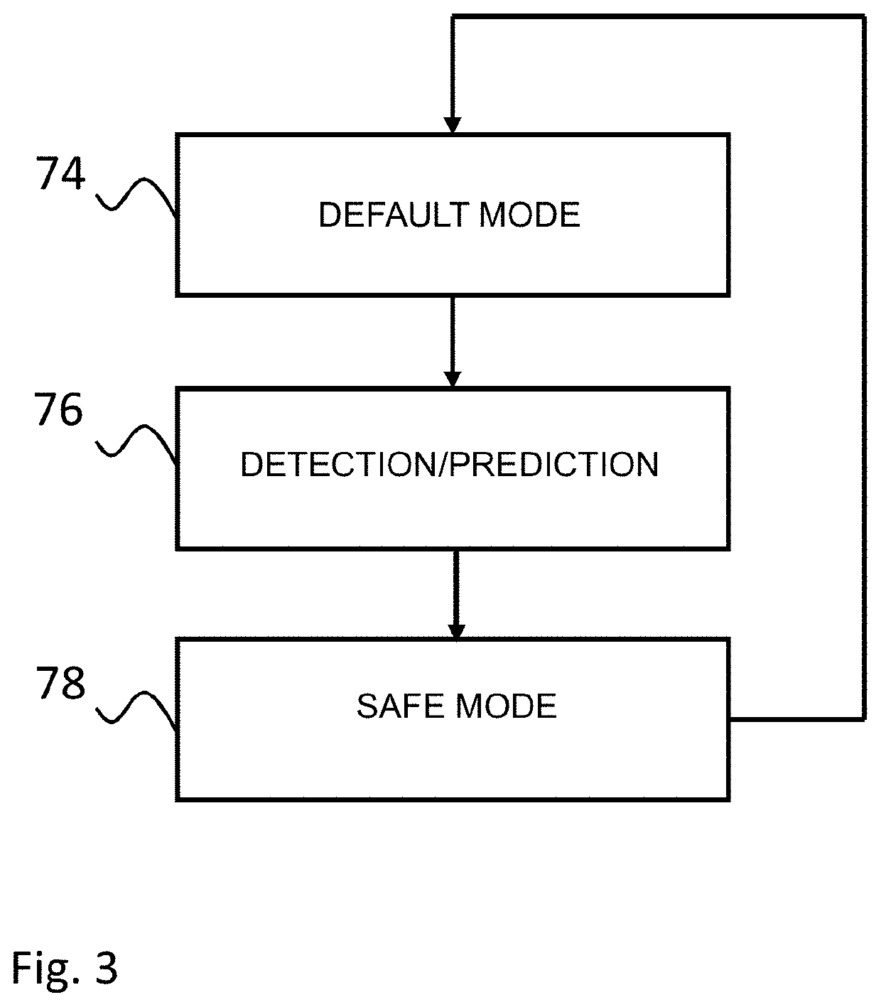
An electronically commutated hydraulic machine is coupled to a drivetrain. Working chambers of the hydraulic machine are connected to low and high pressure manifold through electronically controlled valves. The phase of opening and closing of the valves has a default. In order to avoid cycle failure due to acceleration events, for example due to backlash in the drivetrain, the phase of opening or closing of the electronically controlled valves is temporarily advanced or retarded from the default timing.

Description

FIELD OF THE INVENTION[0001]The invention relates to machines, including but not limited to vehicles, with drive trains which include electronically commutated hydraulic machines.BACKGROUND TO THE INVENTION[0002]Electronically commutated hydraulic machines (ECMs) comprise one or more working chambers of cyclically varying volume, in which the displacement of fluid through the working chambers is regulated by electronically controllable valves, on a cycle by cycle basis and in phased relationship to cycles of working chamber volume, to determine the net throughput of fluid through the machine.[0003]It is known for such machines to intersperse active cycles of working chamber volume (in which there is a net displacement of working fluid) and inactive cycles of working chamber volume (with no significant net displacement of working fluid) to meet a demand signal. Active cycles may be pumping cycles with a net displacement of working fluid from a low pressure manifold to a high pressure...

Claims


Application Information

Patent Timeline
IPC IPC(8): F01B1/06F04B1/06
CPCF04B1/06F01B1/0675F04B1/053F04B7/00F04B49/22F04B49/065F03C1/003F03C1/02F03C1/0466F04B1/04F04B1/066F04B7/0076F04B49/005F04B53/001F04B2201/0601F04B2201/1201F04B2201/1208F04B2205/05F04B2205/13F04B17/02
Inventor CALDWELL, NIALLABRAHAMS, DANIELLATHAM, ANDREW
Owner ARTEMIS INTELLIGENT POWER
Learn More