Disc-Type Electrocatalytic Water Treatment Device
a technology of electrocatalysis and water treatment device, which is applied in the direction of water/sewage treatment using germicide/oligodynamic process, water/sludge/sewage treatment, chemistry apparatus and processes, etc. it can solve the problems of affecting the wide application of the technology, and achieve the effect of increasing the loading area per unit volume, reducing the spacing between electrodes, and increasing the reaction mass transfer efficiency and reaction path
- Summary
- Abstract
- Description
- Claims
- Application Information
AI Technical Summary
Benefits of technology
Problems solved by technology
Method used
Image
Examples
exemplary embodiment 1
[0041]Treatment of salt-containing industrial wastewater by disc-type electrocatalytic reactor with titanium anode having coating of ruthenium oxide
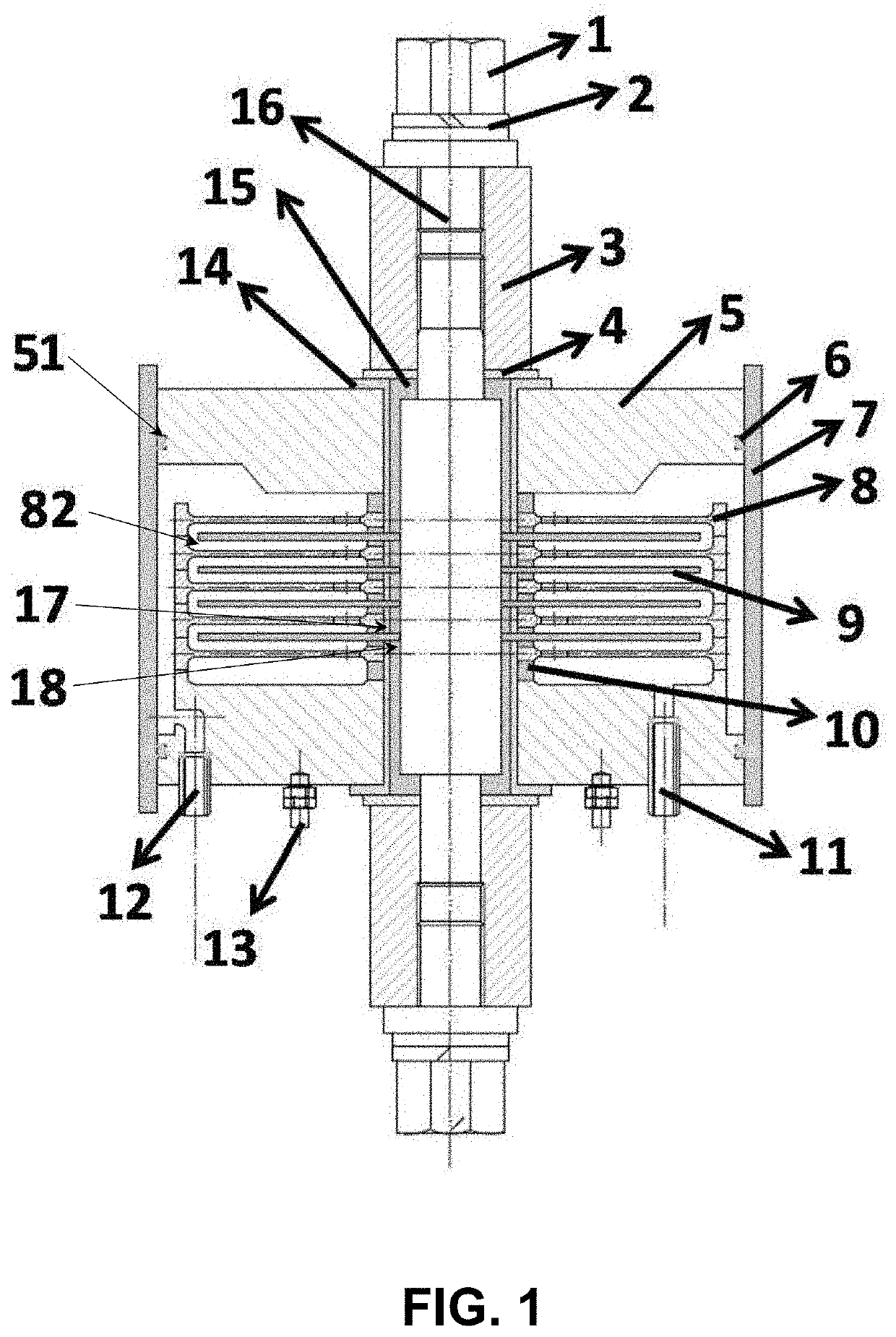
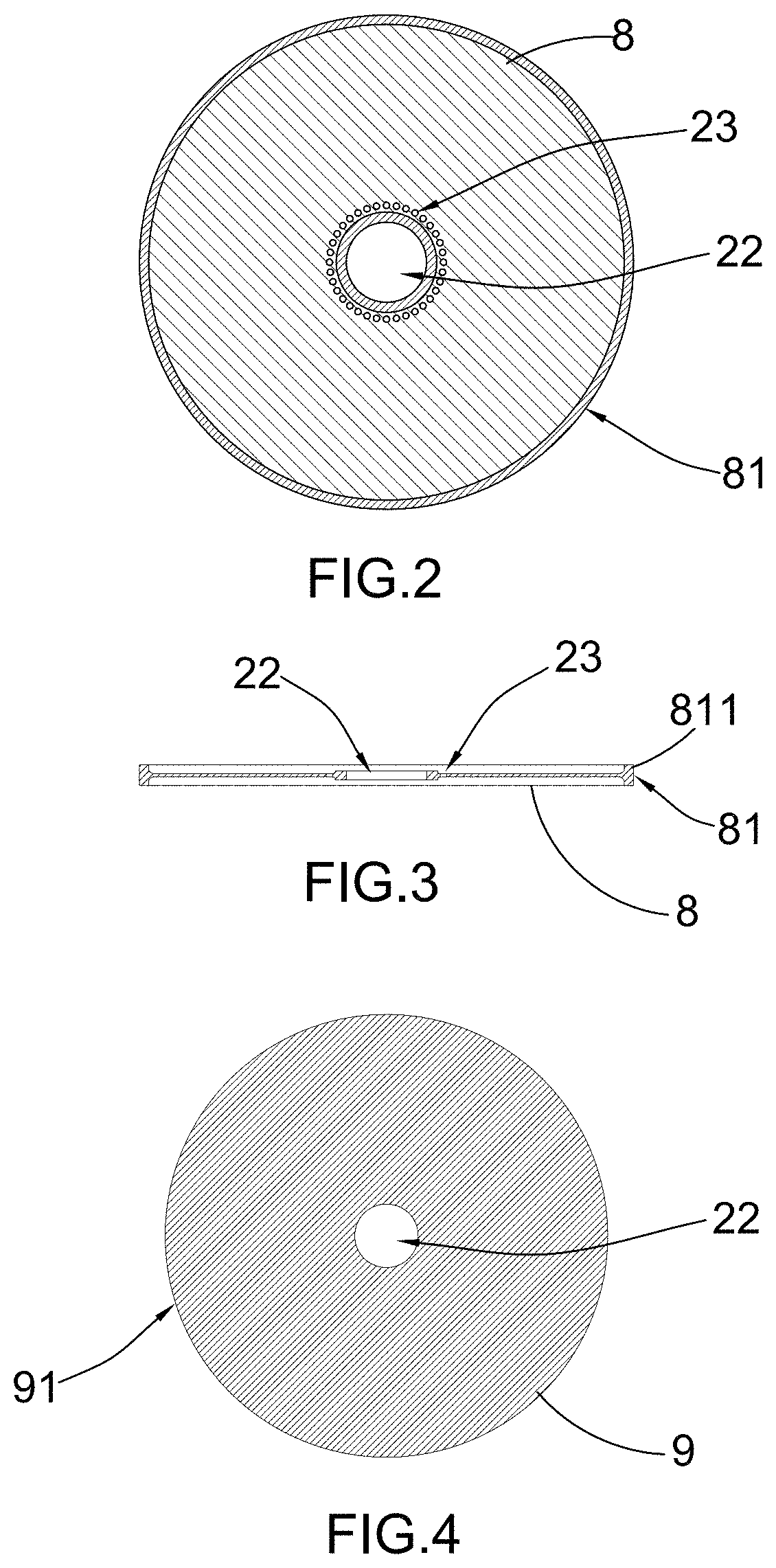
[0042](a) The cathode plate 8 is a stainless steel cathode platen, and the anode plate 9 is a titanium anode with coating of ruthenium oxide.
[0043](b) Utilize a multi-stage centrifugal pump to pump salt-containing industrial wastewater into the water inlet 12 at a flow rate of 1 m / s, and the fluid flows through the passage holes peripheral to the central hole of the cathode plate 8 to form in-and-out circulating flow.
[0044](c) Adjust an applied electric field voltage to 2.0V and a current density to 10 mA / cm2.
[0045](d) Take a sample from the water outlet 11 after 1 hour of stable operation and detect water color, ammonia nitrogen, and COD indicators.
[0046]For the inlet water, the COD is 483 mg / L and the ammonia nitrogen is 232 mg / L. After treatment, the chromaticity in the water can be completely removed, the effluent COD is reduced to 4...
exemplary embodiment 2
[0047]Treatment of salt-containing industrial wastewater by disc-type electrocatalytic reactor with titanium anode having coating of lead oxide
[0048](a) The cathode plate 8 is a stainless steel cathode platen, and the anode plate 9 is a titanium anode with coating of lead oxide.
[0049](b) Utilize a multi-stage centrifugal pump to pump salt-containing industrial wastewater into the water inlet 12 at a flow rate of 2 m / s, and the fluid flows through the passage holes peripheral to the central hole of the cathode plate 8 to form an in-and-out circulating flow.
[0050](c) Adjust an applied electric field voltage to 3.0V and a current density to 20 mA / cm2.
[0051](d) Take a sample from the water outlet 11 after 1 hour of stable operation and detect water color, ammonia nitrogen, and COD indicators.
[0052]For the inlet water, the COD is 483 mg / L and the ammonia nitrogen is 232 mg / L. After treatment, the chromaticity in the water can be completely removed, the effluent COD is reduced to 45 mg / L,...
exemplary embodiment 3
[0053](a) The cathode plate 8 is a stainless steel cathode platen, and the anode plate 9 is a titanium anode with coating of antimony-tin oxide.
[0054](b) Utilize a multi-stage centrifugal pump to pump salt-containing industrial wastewater into the water inlet 12 at a flow rate of 3 m / s, and the fluid flows through the passage holes peripheral to the central hole of the cathode plate 8 to form an in-and-out circulating flow.
[0055](c) Adjust an applied electric field voltage to 4.0V and a current density to 30 mA / cm2.
[0056](d) Take a sample from the water outlet 11 after 1 hour of stable operation and detect water color, ammonia nitrogen, and COD indicators.
[0057]For the inlet water, the COD is 483 mg / L and the ammonia nitrogen is 232 mg / L. After treatment, the chromaticity in the water can be completely removed, the effluent COD is reduced to 42 mg / L, and the ammonia nitrogen is reduced to 1.2 mg / L, reaching the first-level standard for comprehensive wastewater discharge.
PUM
| Property | Measurement | Unit |
|---|---|---|
| COD | aaaaa | aaaaa |
| COD | aaaaa | aaaaa |
| outer diameter | aaaaa | aaaaa |
Abstract
Description
Claims
Application Information
 - R&D
- Intellectual Property
- Life Sciences
- Materials
- Tech Scout
- Unparalleled Data Quality
- Higher Quality Content
- 60% Fewer Hallucinations
Browse by: Latest US Patents, China's latest patents, Technical Efficacy Thesaurus, Application Domain, Technology Topic, Popular Technical Reports.
© 2025 PatSnap. All rights reserved.Legal|Privacy policy|Modern Slavery Act Transparency Statement|Sitemap|About US| Contact US: help@patsnap.com


