Undercut Processing Mechanism, Mold For Molding, And Molded Article
a processing mechanism and molding technology, applied in the field of undercut processing mechanism, mold for molding, molded articles, can solve the problems of ejection operation, inability to properly remove the molded product from the forming mold, etc., and achieve the effect of convenient deformation
- Summary
- Abstract
- Description
- Claims
- Application Information
AI Technical Summary
Benefits of technology
Problems solved by technology
Method used
Image


Examples
first embodiment
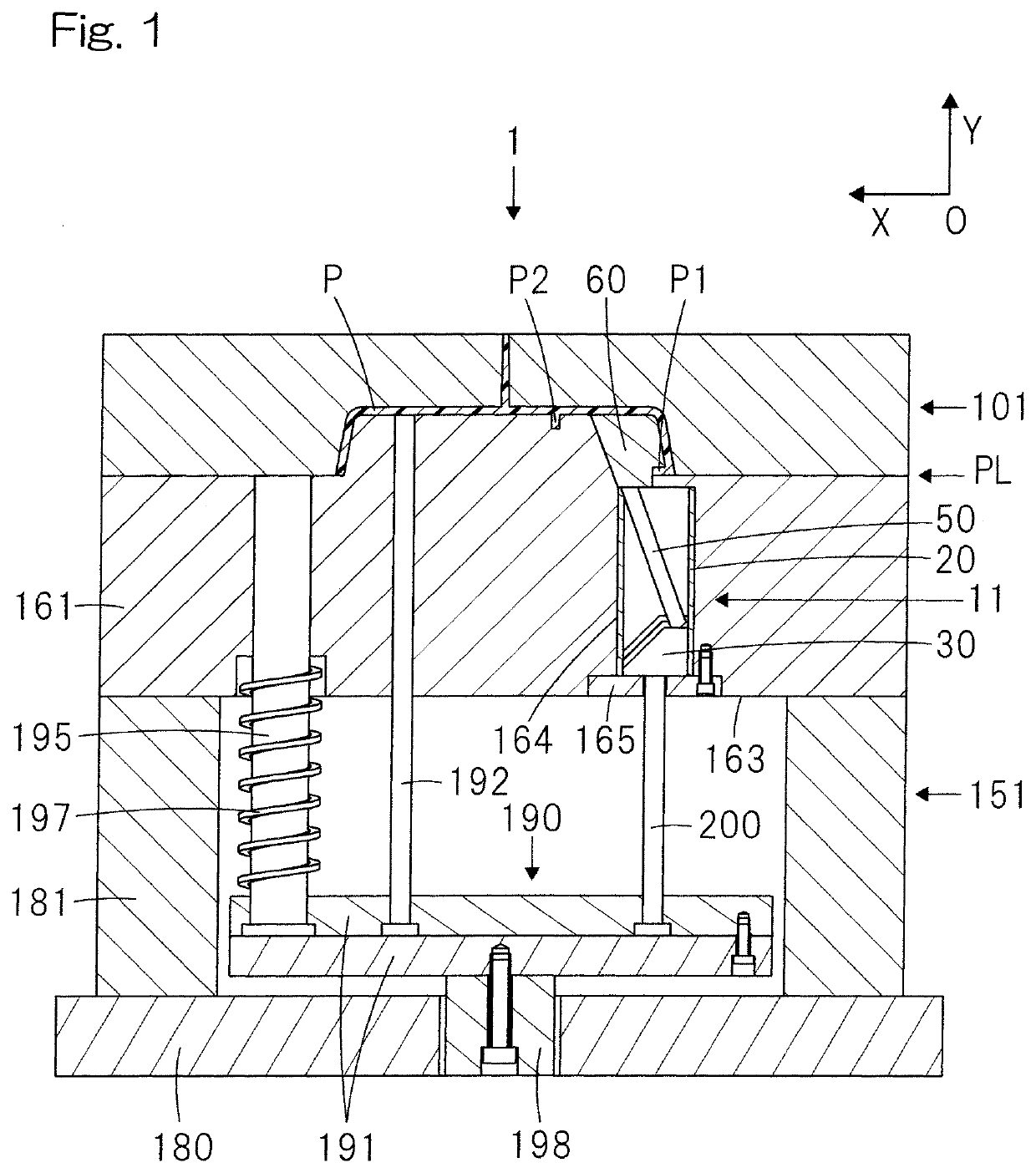
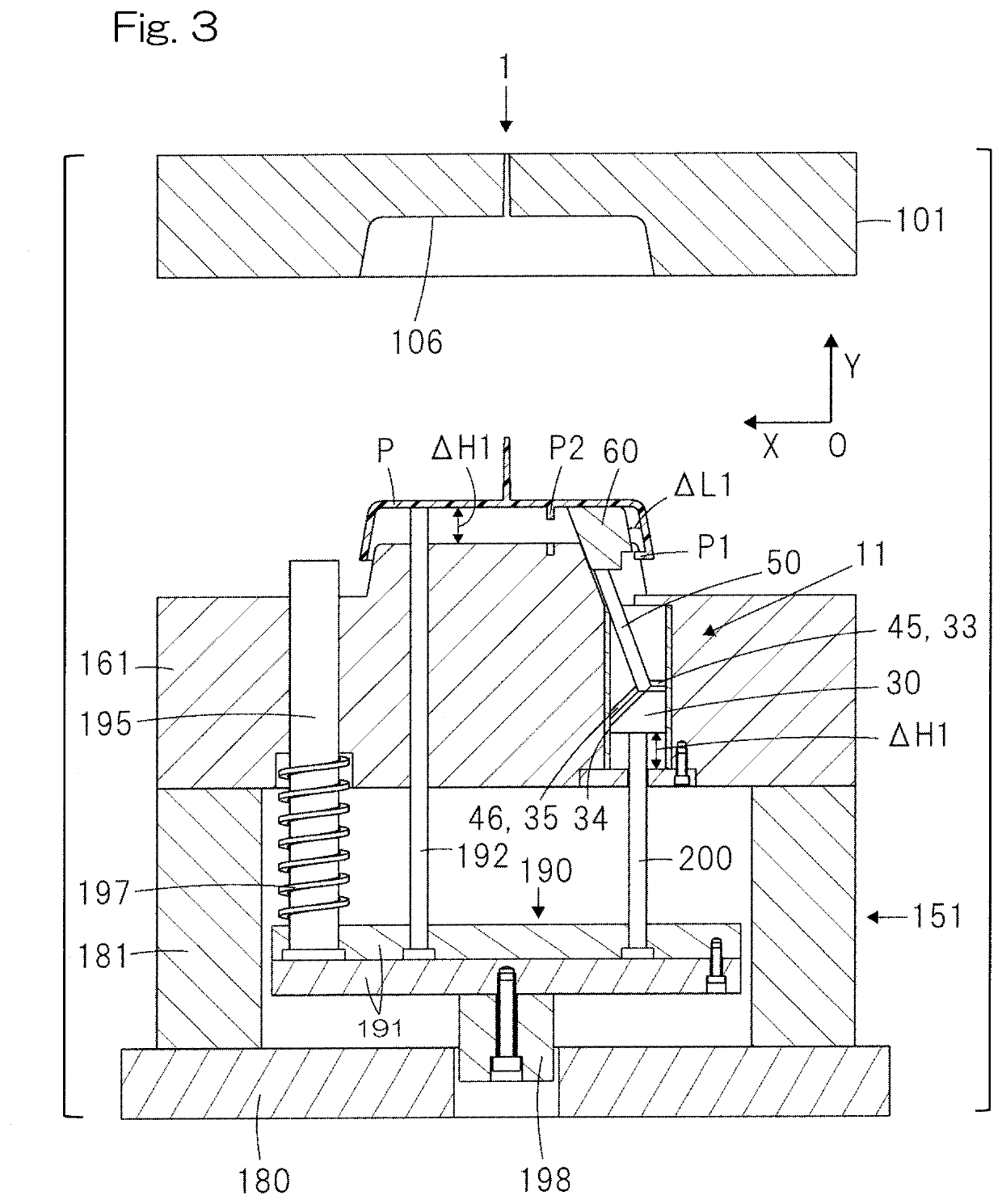
[0032]FIG. 1 and FIG. 2 are sectional views of a forming mold 1 according to the present invention at the time of mold clamping and after mold opening, respectively. FIG. 3 to FIG. 5 are sectional views of the forming mold 1 during an operation of ejecting a molded product P.
[0033]As in a known injection mold, the forming mold 1 according to the first embodiment of the present invention includes: a fixed die 101 for forming the outer surface side of the molded product P; a movable die 151 for forming the inner surface side of the molded product P; and an undercut processing mechanism 11. For convenience sake, the fixed die 101 side in FIG. 1 is defined as upper side and the movable die 151 side is defined as lower side. In addition, in the following description, a left side refers to the left side in FIG. 1, and a right side refers to the side opposite thereto, unless otherwise specified.
[0034]The fixed die 101 has a cavity 106 for forming the outer surface side of the molded produc...
second embodiment
[0088]In the forming mold 2 and the undercut processing mechanism 12 of the second embodiment, the first molding core 65 is moved so as to be pulled off from the undercut portion P1, and then, the first molding core 65 is further moved away from the molded product P. Thereafter, the molded product P is ejected. Therefore, it is possible to easily and assuredly demold the molded product P even if the molded product P has a protruding portion located at a pull-off-direction side from the undercut portion P1.
[0089]FIG. 11 is a sectional view of a forming mold 3 according to the third embodiment of the present invention at the time of mold clamping. FIG. 12 and FIG. 13 are sectional views of the forming mold 3 during mold opening. FIG. 14 is a sectional view of the forming mold 3 before ejection of the molded product P. FIG. 15 is a sectional view of the forming mold 3 during an operation of ejecting the molded product P. The same components as those of the forming mold 1 according to t...
third embodiment
[0115]The forming mold 3 and the undercut processing mechanism 13 of the third embodiment have the following feature: the protrusion 45 forming the first engagement element guides the sliding piece 50 so that the molding core 60 is partially detached from the undercut portion P1; and the protrusion 46 forming the second engagement element guides the sliding piece 50 so that the molding core 60 in a process of being detached from the undercut portion P1 continues being detached from the undercut portion P1 and moves away from the molded product P.
[0116]However, from an overall perspective, the molding core 60 is moved so as to be detached from the undercut portion P1, and then, the molding core 60 is further moved away from the molded product P. In view of this, the forming mold 3 and the undercut processing mechanism 13 of the third embodiment is the same as the forming molds 1, 2 and the undercut processing mechanisms 11, 12 of the first and second embodiments. In the forming molds...
PUM
 Abstract
Description
Claims
Application Information
 - R&D Engineer
- R&D Manager
- IP Professional
- Industry Leading Data Capabilities
- Powerful AI technology
- Patent DNA Extraction
Browse by: Latest US Patents, China's latest patents, Technical Efficacy Thesaurus, Application Domain, Technology Topic.
© 2024 PatSnap. All rights reserved.Legal|Privacy policy|Modern Slavery Act Transparency Statement|Sitemap