
Method for modeling three-dimensional object

a three-dimensional object and object technology, applied in the direction of additive manufacturing processes, manufacturing tools, layer means, etc., can solve the problems of increasing the size of the apparatus, increasing the cost, and deteriorating the impression of the outward appearance so as to increase the modeling speed of the three-dimensional object

Inactive Publication Date: 2020-04-30
MIMAKI ENG
View PDF0 Cites 2 Cited by
  • Summary
  • Abstract
  • Description
  • Claims
  • Application Information

AI Technical Summary

Benefits of technology

This approach enables faster modeling of colored 3D objects with improved surface uniformity and precision, maintaining the appearance quality without the need for additional heads, thus enhancing both speed and cost-effectiveness.

Problems solved by technology

In this case, however, the apparatus becomes larger and the cost increases, which are inevitable.
However, in this case, if a color of a surface of the three-dimensional object is too non-uniform, for example, an impression on an outward appearance of the three-dimensional object may be deteriorated.
In particular, when the coloring is not performed after the modeling, an impression on an outward appearance of a final product may be deteriorated.
In this case, however, there are concerns that if the adhesiveness of the support layer to the mounting table is excessively high, it may be difficult to detach the three-dimensional object from the mounting table after the completion of the modeling.
Also, the force is applied beyond necessity upon the detachment, so that the three-dimensional object may be damaged.

Method used


Image

  • Method for modeling three-dimensional object
  • Method for modeling three-dimensional object
  • Method for modeling three-dimensional object

Examples


Embodiment Construction

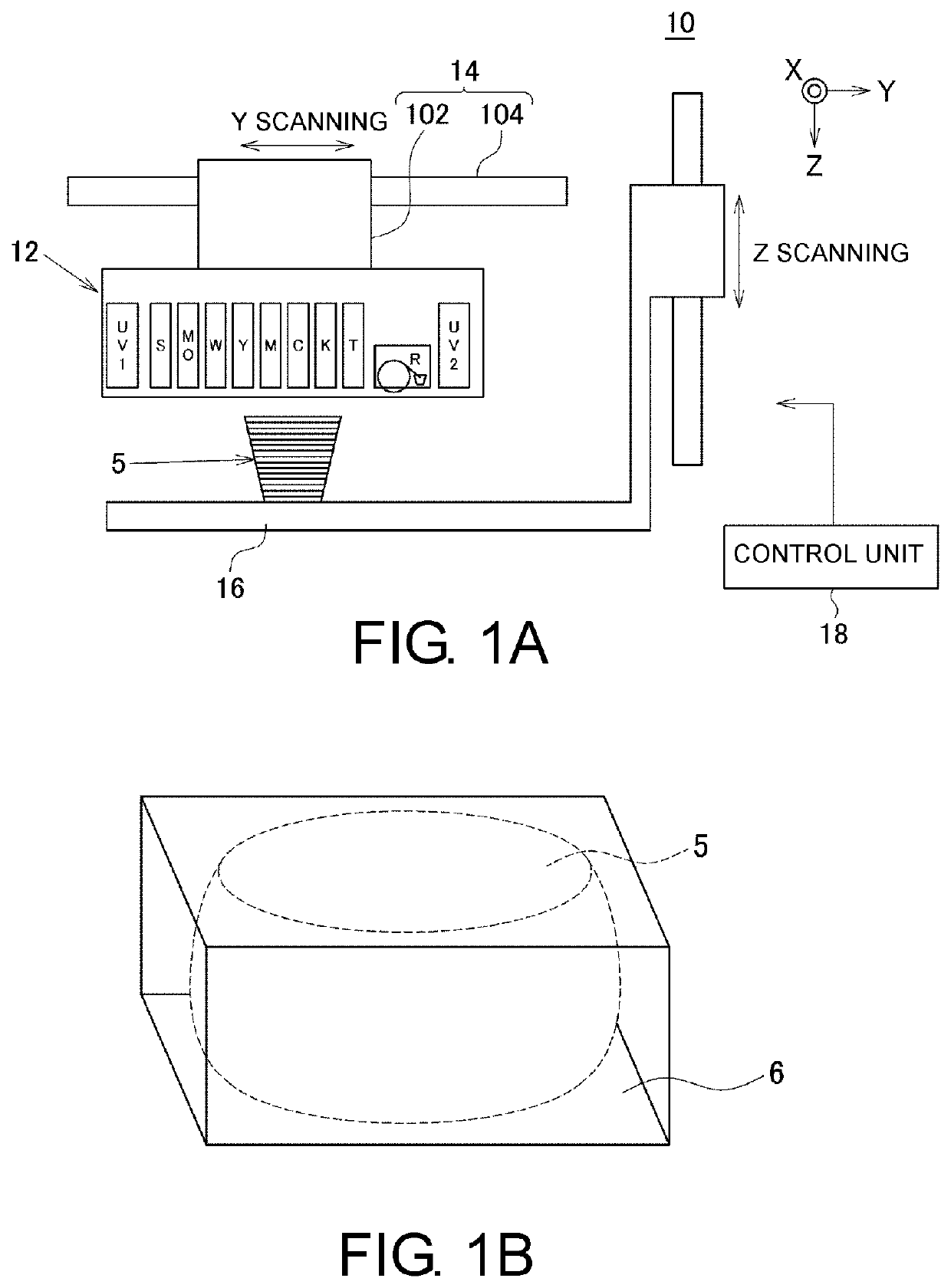
[0059]Hereinafter, an illustrative embodiment of the present disclosure will be described with reference to the drawings. FIGS. 1A and 1B illustrate an example of an apparatus 10 for modeling a three-dimensional object according to an illustrative embodiment of the present disclosure. FIG. 1A illustrates an example of a configuration of main parts of the apparatus 10 for modeling a three-dimensional object, and FIG. 1B illustrates an example of a three-dimensional object 5 that is to be modeled by the apparatus 10 for modeling a three-dimensional object.

[0060]In this illustrative embodiment, the apparatus 10 for modeling a three-dimensional object is an apparatus for modeling the three-dimensional object 5 by a lamination modeling method. In this case, the lamination modeling method is a method of overlapping a plurality of layers to model the three-dimensional object 5. Also, the three-dimensional object 5 is a three-dimensional structure, for example.

[0061]Also, in this illustrati...


PUM

PropertyMeasurementUnit
heightaaaaaaaaaa
thicknessaaaaaaaaaa
thicknessaaaaaaaaaa

Abstract

An apparatus for modeling a three-dimensional object is provided, and includes multiple heads for colored inks, a curing unit, a flattening roller unit, and a control unit. When coloring a surface of the three-dimensional object, the control unit enables the multiple heads for colored inks to discharge ink droplets, based on an image, to an outer periphery area of the three-dimensional object, which is an area of which a color can be visibly recognized from an outside of the three-dimensional object. When not coloring the surface of the three-dimensional object on the basis of the image, the control unit enables at least one of the heads for colored inks to discharge the ink droplets to an inner area positioned at an inner side of the outer periphery area. An ink layer of the inner area formed by the colored inks is flattened by the flattening roller unit.

Description

CROSS-REFERENCE TO RELATED APPLICATIONS[0001]This application is a continuation application of and claims the priority benefit of a prior application Ser. No. 14 / 791,485, filed on Jul. 6, 2015. The prior application Ser. No. 14 / 791,485 claims the priority benefit of Japan application serial no. 2014-139658, filed on Jul. 7, 2014, and No. 2015-099508, filed on May 14, 2015. The entirety of each of the above-mentioned patent applications is hereby incorporated by reference herein and made a part of this specification.TECHNICAL FIELD[0002]The present disclosure relates to an apparatus for modeling a three-dimensional object and a method for modeling a three-dimensional object.DESCRIPTION OF THE BACKGROUND ART[0003]In recent years, a 3D printer configured to model a three-dimensional object has been used for a variety of using applications. Also, a method (inkjet lamination method) of modeling a three-dimensional object by discharging a material for a three-dimensional object from an in...

Claims


Application Information

Patent Timeline
Patent Type & Authority Applications(United States)
IPC IPC(8): B29C64/00B29C64/209B33Y50/02B33Y30/00B29C64/321B29C64/10B29C64/188B41J2/145B41J3/407B29C64/106B29C64/205B29C64/393B33Y10/00B29C64/124B29C64/112B29C64/307B29C64/20
CPCB33Y10/00B29K2995/0021B41J2/145B33Y30/00B29C64/188B41J3/4073B29C64/112B29C64/321B29C64/205B29C64/393B29C64/106B29C64/20B29C64/124B29C64/10B29C64/00B29C64/307B29C64/209B33Y50/02
Inventor HAKKAKU, KUNIOIKEDA, AKIRA
Owner MIMAKI ENG
Learn More