Air purifier housing

a technology for air purifiers and housings, applied in mechanical equipment, gearing, separation processes, etc., can solve the problems of difficult replacement of filter elements in air purifier housings, affecting public health in populated public places, and deteriorating urban air quality in china, so as to achieve convenient replacement and easy and convenient assembly and disassembly.

Active Publication Date: 2020-04-02
AIRPLOVE (XIAMEN) ELECTRONICS CO LTD
View PDF0 Cites 5 Cited by
  • Summary
  • Abstract
  • Description
  • Claims
  • Application Information

AI Technical Summary

Benefits of technology

[0029]By adoption of the above technical solution, the invention has the following beneficial effects:
[0030]When the filter element is installed, the filter element is placed on the outer cover which is then inserted into the insertion grooves of the bottom bracket through the insertion rods, and then the driving part of the limiting structure is controlled to drive the inner container protrusions to be inserted into the installation grooves of the insertion rods via the recessing openings of the insertion grooves to realize limiting, so that the outer cover is fixed and cannot be pulled out. When the filter element needs to be replaced, the driving part of the limiting structure is controlled to drive the inner container protrusions to disengage from the installation grooves of the insertion rods to retreat into the center cavity, so that the outer cover is released and can be disassembled, and the filter element can be replaced conveniently. The air purifier housing has the advantages of being easy and convenient to assemble and disassemble.

Problems solved by technology

In recent years, the frequent occurrence of hazy and dusty air leads to the deterioration of urban air quality in China.
As is known to all, certain dust particles, bacteria and viruses in air are harmful to human bodies, poisonous and harmful gases will be released within a certain time after home decoration, and harmful bacteria and viruses spreading in densely-populated public places may also do harm to public health.
However, the filter element in existing air purifier housings is difficult to replace.

Method used


Image

  • Air purifier housing
  • Air purifier housing
  • Air purifier housing

Examples


embodiment 1

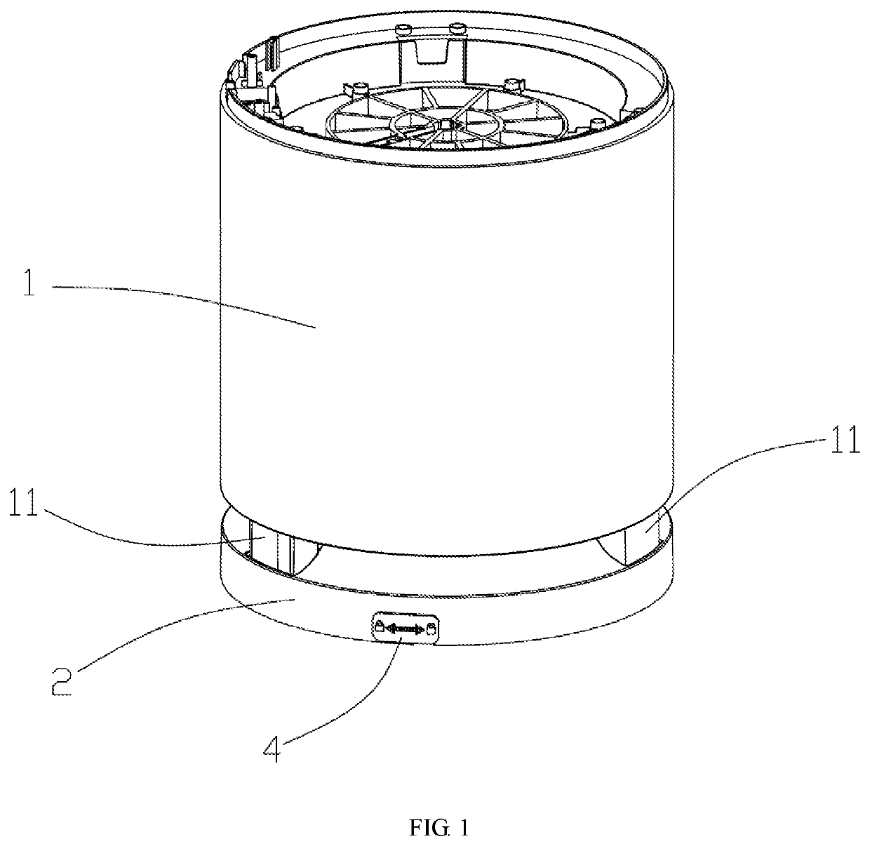
[0052]As shown in FIGS. 1-4, the air purifier housing in this embodiment comprises an outer cover 1, a bottom bracket 2 and a rotary convex platform 3, wherein a circular center cavity 21 which is open downwards is formed in the bottom bracket 2, at least one installation part 211 extending inwards is formed on the inner wall of the center cavity 21, and the rotary convex platform 3 is adaptively and rotatably arranged in the center cavity 21 and is provided with recessing regions 31 allowing the installation parts 211 to be recessed therein and having a recessing area larger than the area of the installation parts 211; an L-shaped groove 2111 having a first end stretching to the top of the bottom bracket and a second end stretching into the center cavity 21 is formed in each installation part 211, and the L-shaped grooves 2111 serve as the insertion groove; the second ends of the L-shaped grooves 2111 are formed with the recessing openings and stretch into the center cavity 21; the...

embodiment 2

[0063]As shown in FIGS. 5-14, the air purifier housing in this embodiment comprises an outer cover 1 and a bottom bracket 2, wherein a center cavity 21 which is open downwards is formed in the bottom bracket 2, insertion grooves 211 are formed in the bottom bracket 2, recessing openings 2111 stretching into the center cavity 21 are formed in side walls of the insertion grooves 211, insertion rods 11 are fixedly arranged on the outer cover 1, the outer cover 1 is inserted into the insertion grooves 211 of the bottom bracket 2 through the insertion rods 11, and installation grooves 111 corresponding to the recessing openings 2111 are formed in the insertion rods 11.

[0064]A limiting structure is arranged in the center cavity 21 of the bottom bracket 2 and comprises swing arms 43, a driving part and inner container protrusions 44, wherein the swing arms are pivoted to first stationary shafts 201 in the center cavity 21, the inner container protrusions 44 are connected with the swing arm...

embodiment 3

[0082]The air purifier housing in this embodiment is basically identical with the air purifier housing in Embodiment 2 in structure and differs from the air purifier housing in Embodiment 2 in the following aspects: as shown in FIG. 15, in this embodiment, the pin 41 is pressed by an elastic base plate 47 to move instead of being controlled by the toggle button 451. Particularly, the driving part further comprises the elastic base plate 47, which covers a bottom opening of the center cavity 21 of the bottom bracket 2 and is fixedly connected with the pin 41, and the elastic base plate 47 can be elastically pressed towards the interior of the center cavity 21 to drive the pin 41 to be movably inserted. When the inner container protrusions 44 need to return to the second position, the elastic base plate 47 is pressed to elastically deform inwards (towards the interior of the center cavity 21) and then drives the pin 41 to be inserted, then the connecting rods 46 are driven to move tow...


PUM

PropertyMeasurementUnit
areaaaaaaaaaaa
forceaaaaaaaaaa
elasticaaaaaaaaaa

Abstract

An air purifier housing comprises an outer cover and a bottom bracket with a center cavity which is open downwards and insertion grooves, recessing openings stretching into the center cavity are formed in side walls of the insertion grooves, insertion rods are fixed on the outer cover, which is inserted into the insertion grooves through the insertion rods; installation grooves corresponding to the recessing openings are in the insertion rods; and a limiting structure is in the center cavity and comprises a driving part and inner container protrusions which correspond to the recessing openings, and the driving part connects with the inner container protrusions and drives them to reach a first position where the inner container protrusions stretch out of the insertion grooves to be inserted into the installation grooves of the insertion rods or to reach a second position where the inner container protrusions retreat into the center cavity.

Description

BACKGROUND OF THE INVENTION1. Technical Field[0001]The invention relates to the technical field of air purifiers, in particular to an air purifier housing.2. Description of Related Art[0002]In recent years, the frequent occurrence of hazy and dusty air leads to the deterioration of urban air quality in China. As is known to all, certain dust particles, bacteria and viruses in air are harmful to human bodies, poisonous and harmful gases will be released within a certain time after home decoration, and harmful bacteria and viruses spreading in densely-populated public places may also do harm to public health. With the improvement of living standards, people are paying more and more attention to the living environment around and particularly to the indoor air quality, and various air purifiers are adopted to improve the indoor air quality so as to meet the higher and higher requirements for the surrounding air quality and the indoor air quality. As a result, a large number of air purif...

Claims


Application Information

Patent Timeline
Patent Type & Authority Applications(United States)
IPC IPC(8): B01D46/00F16H21/44B01D46/42
CPCB01D46/0005F16H21/44A61L9/16B01D46/4227A61L2209/14B01D46/0004B01D2265/022B01D2265/026
Inventor CHEN, JUEYUANLIN, ZHANGCANXU, JINBOLEI, TINGPING
Owner AIRPLOVE (XIAMEN) ELECTRONICS CO LTD
Why Eureka
Try Eureka