
Method for creating demand response determination model for HVAC system and method for implementing demand response

a demand response and determination model technology, applied in the direction of lighting and heating apparatus, heating types, instruments, etc., can solve the problem of particularly difficult to employ the demand response in the hvac system in a multi-zone building, and achieve the effect of easy and quick production

Inactive Publication Date: 2020-03-12
SEOKYOUNG SYST
View PDF0 Cites 10 Cited by
  • Summary
  • Abstract
  • Description
  • Claims
  • Application Information

AI Technical Summary

Benefits of technology

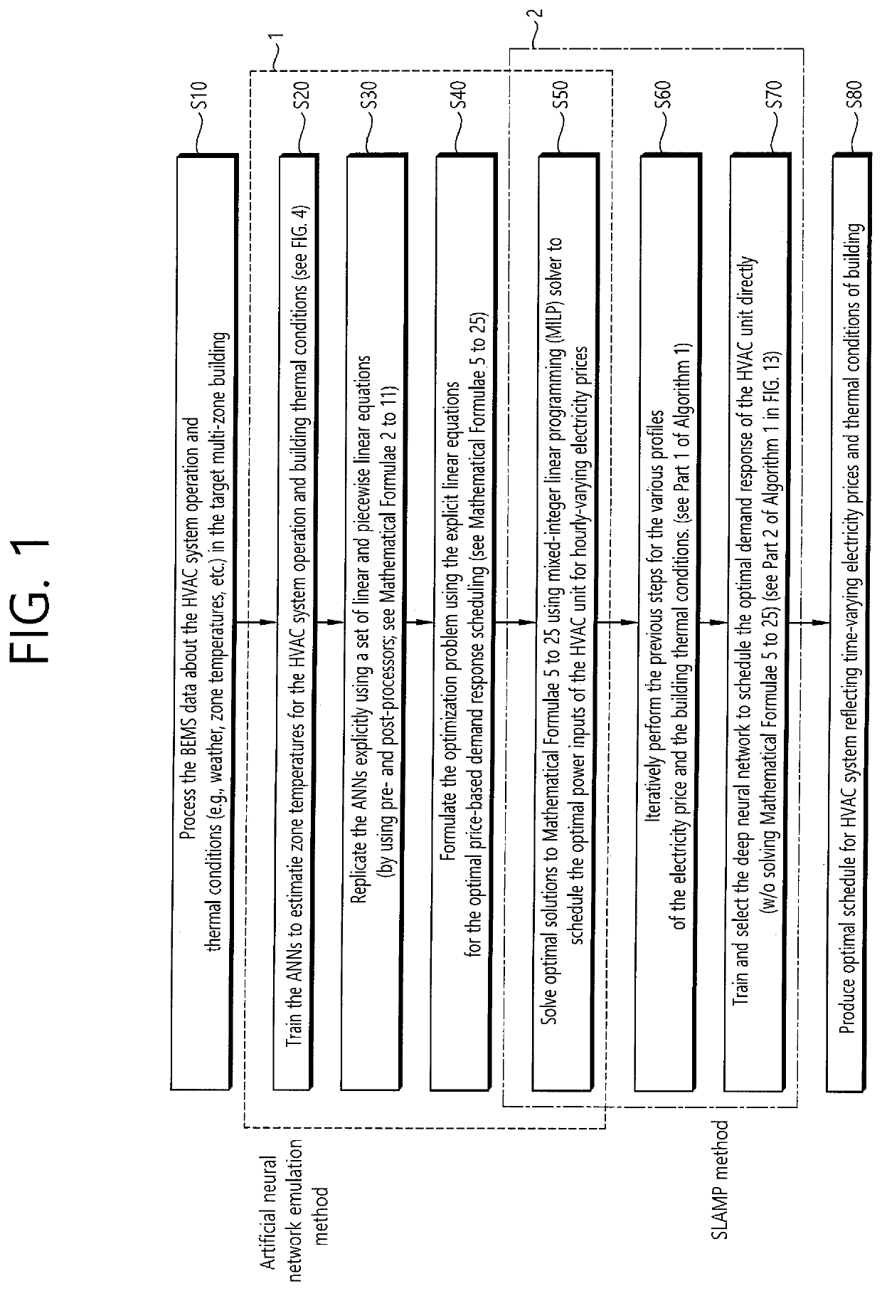
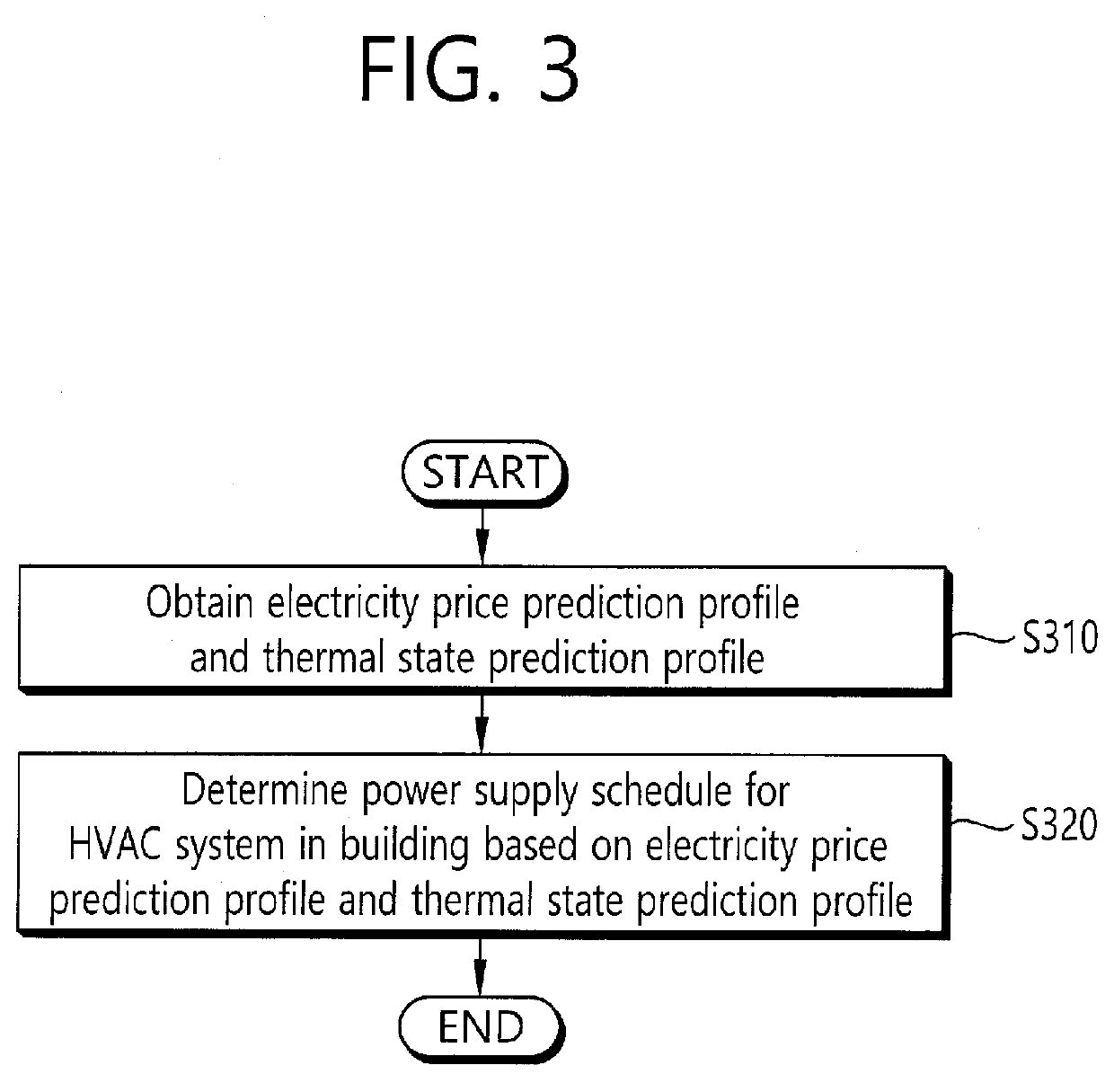
The present invention provides a method for creating a demand response determination model for an HVAC system using machine learning to optimize power consumption based on time-varying electricity prices. This model can easily and quickly produce an optimal schedule of input power to the HVAC system, minimizing total electricity cost and the sum of surpluses from a predetermined boundary temperature. Overall, this invention helps to manage energy utilization and save energy in a cost-effective way.

Problems solved by technology

However, it is particularly difficult to employ the demand response in the HVAC system in a multi-zone building, because using an HVAC system as a demand response resource requires different temperature models for each zone dependent on the thermal conditions of the building and facility management in the building and these models should reflect the physical characteristics in detail.

Method used


Image

  • Method for creating demand response determination model for HVAC system and method for implementing demand response
  • Method for creating demand response determination model for HVAC system and method for implementing demand response
  • Method for creating demand response determination model for HVAC system and method for implementing demand response

Examples


Embodiment Construction

[0040]Examples of various embodiments are illustrated and described further below. It will be understood that the description herein is not intended to limit the claims to the specific embodiments described. On the contrary, it is intended to cover alternatives, modifications, and equivalents as may be included within the spirit and scope of the present disclosure as defined by the appended claims.

[0041]It will be understood that, although the terms “first”, “second”, “third”, and so on may be used herein to describe various elements, components, regions, layers and / or sections, these elements, components, regions, layers and / or sections should not be limited by these terms. These terms are used to distinguish one element, component, region, layer or section from another element, component, region, layer or section. Thus, a first element, component, region, layer or section described below could be termed a second element, component, region, layer or section, without departing from ...


PUM


Abstract

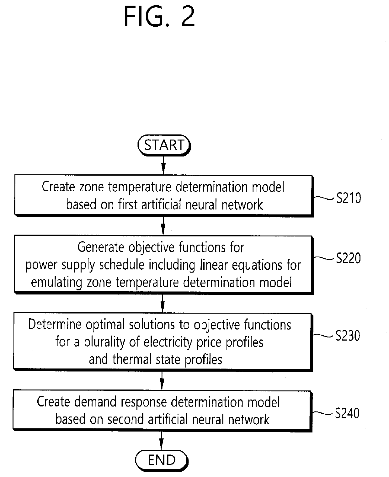
A method for implementing a demand response (DR) for a HVAC system in a building is provided. The method comprises: creating a zone temperature determination model that outputs temperatures of the building by considering an input power provided to the HVAC system and a thermal state of the building; generating objective functions for a power supply schedule in which optimal solutions vary with electricity prices and the thermal state, wherein the power supply schedule includes linear equations for emulating the zone temperature determination model; determining the optimal solutions to the objective functions based on a plurality of electricity price profiles and thermal state profiles; and creating a demand response determination model for taking the electricity price profiles and the thermal state profiles as input and producing a power supply schedule for the HVAC system as output.

Description

CROSS-REFERENCE TO RELATED APPLICATION[0001]This application is based on and claims the benefit of priority to Korean Patent Application No. 10-2018-0109099, filed on Sep. 12, 2018, the disclosure of which is incorporated herein in its entirety by reference.BACKGROUND OF THE INVENTIONField of the Invention[0002]The present invention relates to implement a demand response for a heating, ventilation, and air-conditioning (HVAC) system in a building, and more particularly, to a method of utilizing a supervised learning for an improved demand response for the HVAC system in the building.Related Art[0003]Buildings have high thermal capacity, and thus heating, ventilation, and air-conditioning (HVAC) systems in the buildings can be used for a demand response (DR). However, it is particularly difficult to employ the demand response in the HVAC system in a multi-zone building, because using an HVAC system as a demand response resource requires different temperature models for each zone depe...

Claims


Application Information

Patent Timeline
Patent Type & Authority Applications(United States)
IPC IPC(8): F24F11/47F24F11/61
CPCF24F11/47F24F2140/60F24F11/61F24F2110/10F24F11/63F24F2110/20F24F2140/50F24F2110/40G05B13/027G05D23/1902G06Q10/04G06Q10/0631G06Q50/06G06N3/08
Inventor SOHN, YOUNGSEOKKIM, YOUNGJINJANG, YE EUN
Owner SEOKYOUNG SYST
Learn More