Redundant power transfer apparatus and control methods

a technology of redundancy power and power transfer, applied in the integration of power network operation systems, emergency power supply arrangements, sustainable buildings, etc., can solve the problems of large volume, high cost, unfavorable design of integrated power supply, etc., and achieve low switching efficiency and high circuit cost.

Active Publication Date: 2020-03-05
DELTA ELECTRONICS INC
View PDF6 Cites 3 Cited by
  • Summary
  • Abstract
  • Description
  • Claims
  • Application Information

AI Technical Summary

Benefits of technology

The present invention provides a redundant power transfer apparatus to solve problems of low switching efficiency and high circuit costs. The apparatus reduces stress on switches, increases reliability, and enables miniaturization of the rear-stage circuit while providing sufficient hold-up time. Additionally, the apparatus is appropriately applied to zero current switching control. The invention also provides a method of controlling the redundant power transfer apparatus to reduce switch stress, lower switching time, increase power transfer efficiency, and miniaturize the rear-stage circuit, among others.

Problems solved by technology

However, the existing redundant power system has the problems of large volume and high costs, and therefore it is not conducive to the design of integrated power supply.

Method used


Image

  • Redundant power transfer apparatus and control methods
  • Redundant power transfer apparatus and control methods
  • Redundant power transfer apparatus and control methods

Examples


Embodiment Construction

[0018]Reference will now be made to the drawing figures to describe the present disclosure in detail. It will be understood that the drawing figures and exemplified embodiments of present disclosure are not limited to the details thereof.

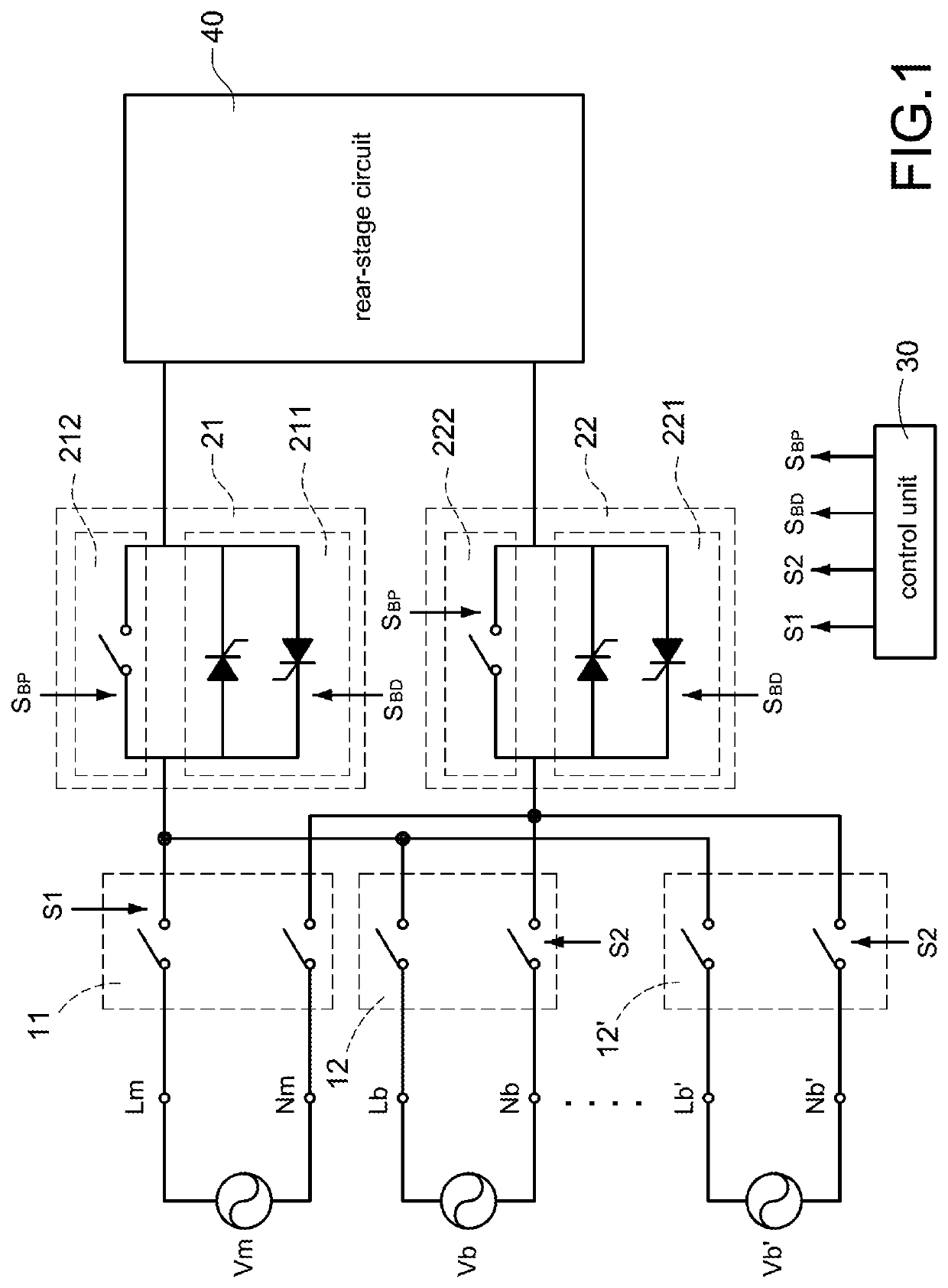
[0019]Please refer to FIG. 1, which shows a block circuit diagram of a redundant power transfer apparatus according to the present disclosure. The redundant power transfer apparatus includes a main loop switch 11, a standby loop switch 12, a first switch assembly 21, a second switch assembly 22, and a control unit 30. The main loop switch 11 is coupled to a main power source Vm. The main power source Vm is, for example but not limited to, an AC utility or a generator for mainly providing the required power to a rear-stage circuit 40. The standby loop switch 12 is coupled to a standby power source Vb. The standby power source Vb is, for example but not limited to, another AC utility, another generator, or an AC power source converted from a renewable...


PUM


Abstract

A redundant power transfer apparatus provides an uninterrupted power transfer for a rear-stage circuit. The redundant power transfer apparatus includes a main loop switch coupled to a main power source, a standby loop switch coupled to a standby power source, and a control unit. The control unit controls the redundant power transfer apparatus to make the main power source or the standby power source supply power to the rear-stage circuit.

Description

BACKGROUNDTechnical Field[0001]The present disclosure relates to a transfer apparatus and control methods, and more particularly to a redundant power transfer apparatus and control methods.Description of Related Art[0002]The statements in this section merely provide background information related to the present disclosure and do not necessarily constitute prior art.[0003]At present, the redundant power system has been widely used in various data centers and server power input stages, and its purpose is to improve the reliability and flexibility of power supply. In recent years, under the requirements of system space and capacity utilization, the redundant circuits have been gradually integrated into the power supply unit from individual units. However, the existing redundant power system has the problems of large volume and high costs, and therefore it is not conducive to the design of integrated power supply.SUMMARY[0004]An objective of the present disclosure is to provide a redund...

Claims


Application Information

Patent Timeline
IPC IPC(8): H02J9/06
CPCH02J9/068H02J9/06H02J3/18H02J9/062Y04S20/20Y02B70/30Y02B10/70
Inventor PENG, TE-CHIHLO, MING-HSIANGCHANG, CHIA-HAO
Owner DELTA ELECTRONICS INC
Why Eureka
Try Eureka