
Method and apparatus for measuring bio-signal using radar

a biosignal and radar technology, applied in the field of biosignal measurement methods and apparatuses, can solve the problems of weak human body signal, limited radio frequency transmission signal power that can be radiated, and easy to be affected by noise and interference from the surrounding

Inactive Publication Date: 2020-02-06
WRT LAB CO LTD
View PDF0 Cites 4 Cited by
  • Summary
  • Abstract
  • Description
  • Claims
  • Application Information

AI Technical Summary

Benefits of technology

The patent describes a way to detect a person's heartbeat rate and waves from a radar signal that includes both breathing and heartbeat signals in real-time.

Problems solved by technology

However, in case of a bio-radar, since a subject to be measured is the human body, radio frequency (RF) transmission signal power that can be radiated is severely limited.
In addition, a signal received from the human body is very weak, and thus it is very vulnerable to noise and interference from the surroundings.
However, such a conventional method extracts an average heartbeat rate during a certain time through frequency detection, but monitoring an interval of a real-time heartbeat waveform is difficult since a pulse of each heartbeat is not monitored in a time axis.
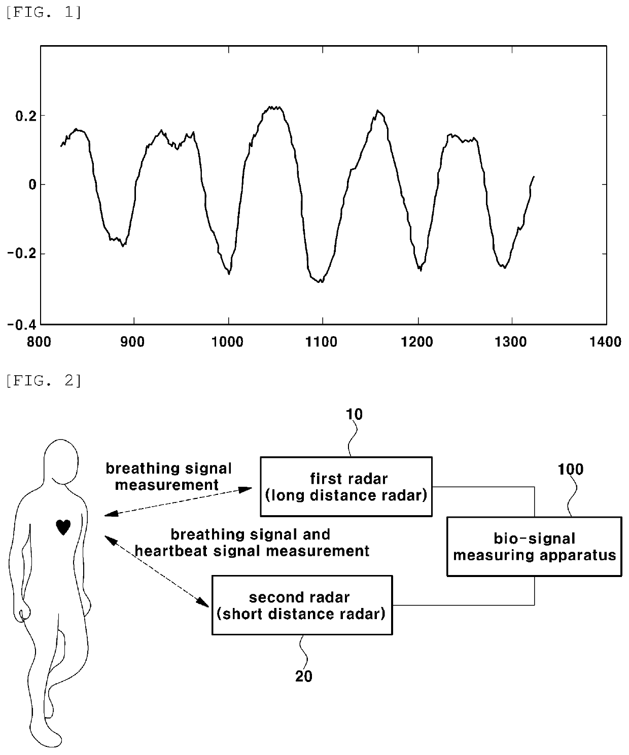
In addition, motions due to breathing are larger than motions due to a heartbeat, and thus accuracy is degraded when detecting a heartbeat waveform in real-time from a radar signal including both breathing and heartbeat signals by using a conventional method.
Accordingly, for patients with arrhythmia where an interval of heartbeat waveform changes in real time, or for a case other than arrhythmia patients when real-time period information of a heartbeat waveform is required, detecting a heartbeat signal by using the conventional method is difficult.

Method used


Image

  • Method and apparatus for measuring bio-signal using radar
  • Method and apparatus for measuring bio-signal using radar
  • Method and apparatus for measuring bio-signal using radar

Examples


Embodiment Construction

[0031]Since the present invention may be modified in various forms, and may have various embodiments, the following exemplary embodiments are illustrated in the accompanying drawings, and are described in detail with reference to the drawings However, this is not intended to limit the present invention to specific embodiments, and the present invention should be construed to encompass various changes, equivalents, and substitutions within the technical scope and spirit of the invention. Like numbers refer to like elements throughout in the description of each drawing.

[0032]Hereinafter, various embodiments of the present invention will be described with reference to the accompanying drawings.

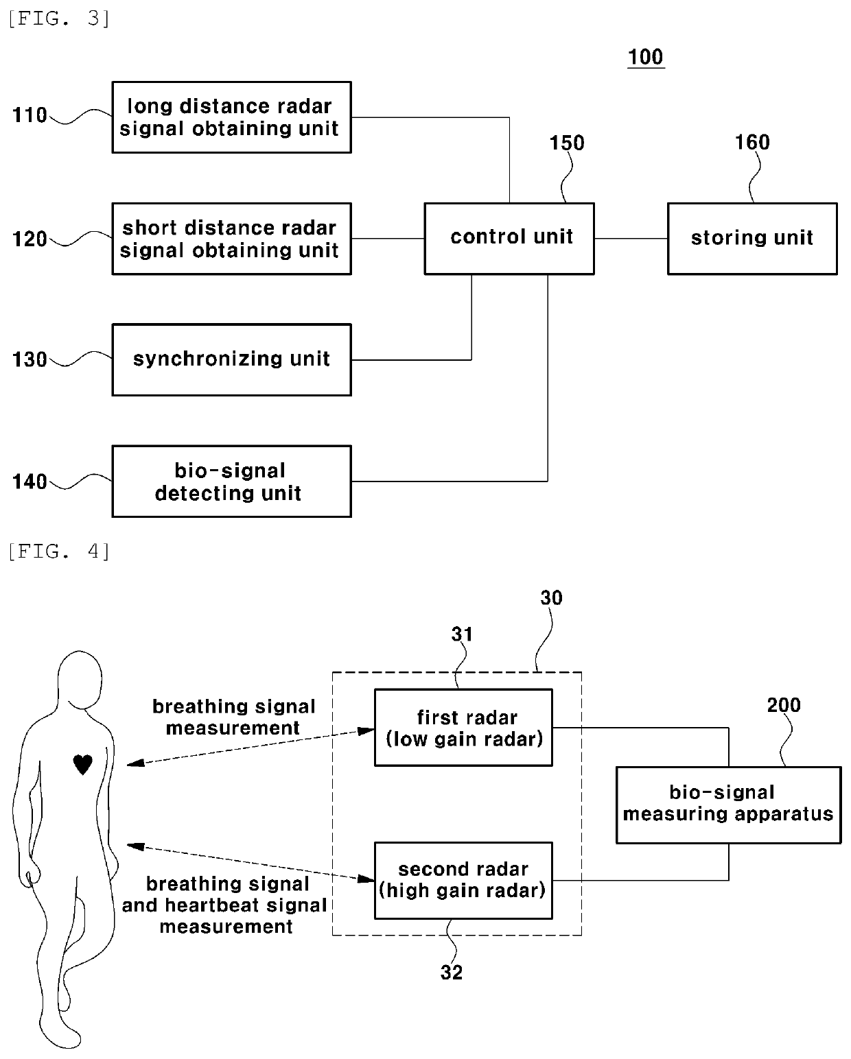
[0033]FIG. 2 is a view showing a configuration of a system for measuring a bio-signal by using a radar according to an embodiment of the present invention.

[0034]A system for measuring a bio-signal by using a radar according to an embodiment of the present invention may include a first radar 10, a...


PUM


Abstract

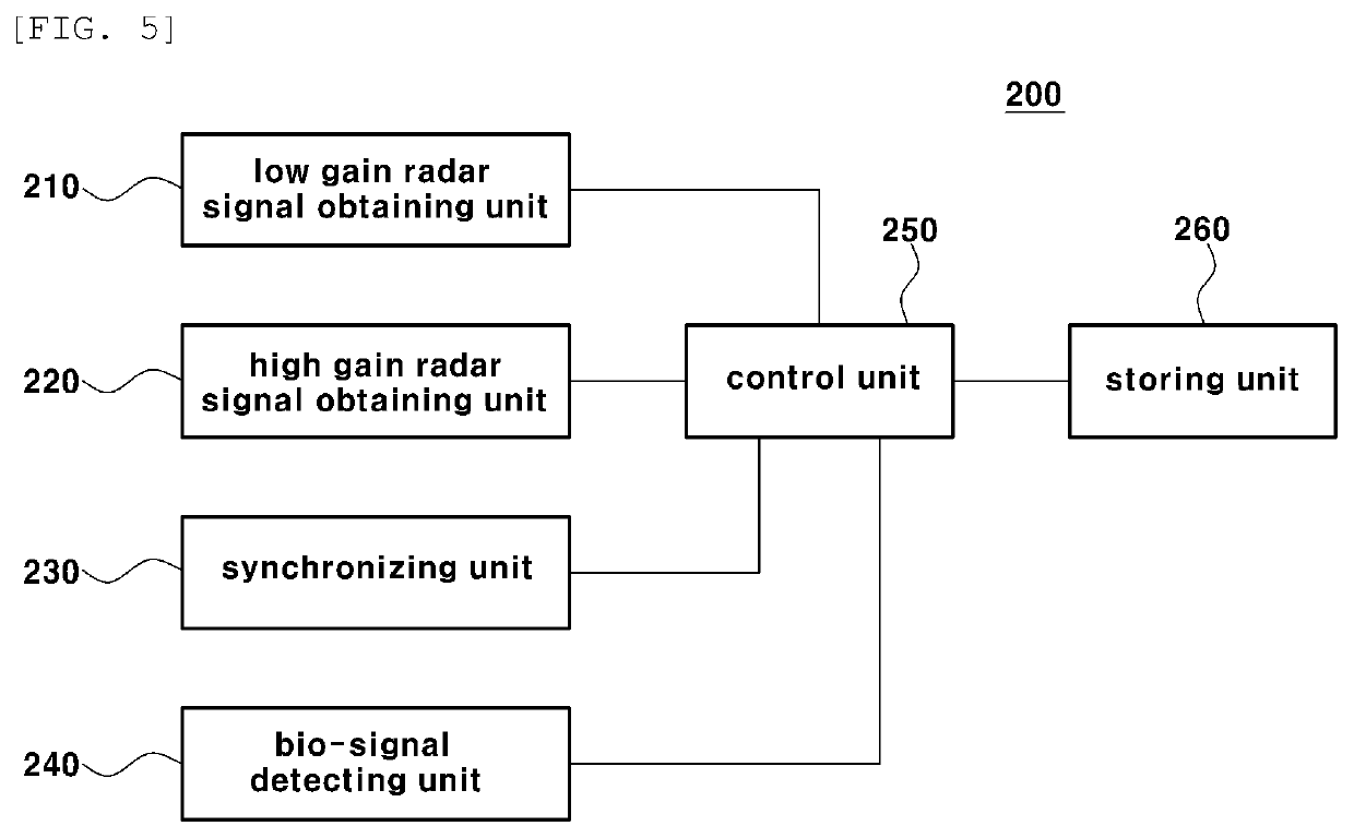
Provided is a method and apparatus for measuring a bio-signal using a radar. An apparatus for measuring a bio-signal using a radar according to an embodiment of the present invention comprises: a first signal acquisition unit for acquiring, from a first radar, a first signal including a first bio-signal measured from a measurement subject, a second signal acquisition unit for acquiring, from a second radar, a second signal including both a second bio-signal and the first bio-signal measured from the measurement subject; a signal synchronization unit for synchronizing the first signal and the second signal and a bio-signal detection unit for calculating the difference between the synchronized first and second signals so as to eliminate the first bio-signal and detect the second bio-signal from the second signal.

Description

TECHNICAL FIELD[0001]The present invention relates to a method and apparatus for measuring a bio-signal by using a radar. More particularly, the present invention relates to a method and apparatus for measuring a bio-signal such as a heartbeat signal by using a plurality of radars.BACKGROUND ART[0002]Recently, research and development of a bio-radar for detecting breathing and heartbeat signals in a non-contact manner is underway.[0003]However, in case of a bio-radar, since a subject to be measured is the human body, radio frequency (RF) transmission signal power that can be radiated is severely limited. In addition, a signal received from the human body is very weak, and thus it is very vulnerable to noise and interference from the surroundings.[0004]Accordingly, a technique is provided where an impulse-radio ultra wide band (IR-UWB) radar (hereinafter, referred as “UWB radar”) is used to measure a bio-signal.[0005]Herein, “ultra wide band (UWB)” is a radio technique that uses a fr...

Claims


Application Information

Patent Timeline
IPC IPC(8): A61B5/024A61B5/00A61B5/0205A61B5/08
CPCA61B5/0004A61B5/0205A61B5/08G01S13/88A61B5/024A61B5/02444A61B5/0507A61B5/0816A61B5/7225A61B2505/07A61B2562/0228G01S7/292G01S7/414G01S7/415G01S13/0209G01S13/10G01S13/87G01S13/62
Inventor CHO, SUNG HOCHOI, JEONG WOOLIM, YOUNG HYOLEE, YU NA
Owner WRT LAB CO LTD
Learn More