Motorized vehicle comprising a connected fork crown

Active Publication Date: 2020-01-23
IRIDER
View PDF0 Cites 2 Cited by
  • Summary
  • Abstract
  • Description
  • Claims
  • Application Information

AI Technical Summary

Benefits of technology

The patent describes a motorized vehicle that can integrate new electronic technologies without affecting its appearance. The fork crown design allows for optimal placement of a cavity and minimizes visual modifications. This allows for the vehicle to have advanced technology without sacrificing its overall appearance.

Problems solved by technology

The expectation of integrating these new technologies can however clash with the absence of bodywork of motorcycles, as well as the desire of motorcycle drivers to have vehicles which are pleasant to look at.
Consequently, adding unsightly external elements to a motorcycle, for example a casing intended to comprise electronic elements, would lead to a disadvantage likely to limit the adoption of new technologies.

Method used


Image

  • Motorized vehicle comprising a connected fork crown
  • Motorized vehicle comprising a connected fork crown
  • Motorized vehicle comprising a connected fork crown

Examples


first embodiment

[0076]In reference to FIG. 3 and the cavity 21 is located between the coupling and clamping housings.

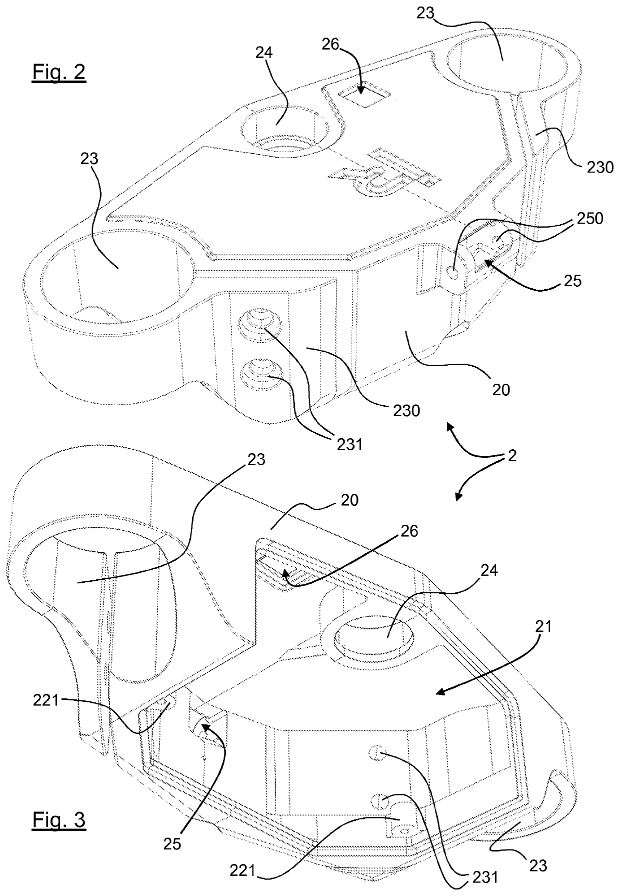
[0077]In reference to FIGS. 2, 3 and 4, the fork crown 2 also has a means for coupling 24 to the steering shaft. This coupling means 24 is formed by the joining of the body 20 and of the cover 22.

[0078]According to FIGS. 2 and 3, the body 20, in complement to the coupling and clamping housings 23, has two clamping pads 230, each intended to be re-clamped onto the body by way of complementary screws of two tapped holes 231 located on these clamping pads. By screwing the complementary screws in the two tapped screws, the fork tubes previously inserted in the coupling and clamping housings 23 are surrounded.

[0079]Such as illustrated by FIGS. 2, 3 and 6, the body 20 also has:[0080]a first communication space 25 with a space located in front and above the fork crown, the fork crown comprising, at the level of this second communication space, an excrescence with means for fixing 250 to a ...

second embodiment

[0118]In reference to FIGS. 7 to 10, the fork crown is described below.

[0119]The upper fork crown 2 has a body 20.

[0120]This body 20 has a cavity 21. The cavity is closed by a cover 22.

[0121]The body 20 also comprises:[0122]coupling and clamping housing 23 intended to receive fork tubes 100;[0123]a means for coupling 24 to the steering shaft.

[0124]Different from the first embodiment, the body 20 has a cavity 21 which is not located between the coupling and clamping housings 23.

[0125]Indeed, the cavity 21 is positioned offset with respect to a central portion 200 of the fork crown 2.

[0126]More specifically, according to this embodiment, the body 20 of the fork crown 2 comprises:[0127]a central portion 200, having coupling and clamping housings 23 as well as the means for coupling 24 to the steering shaft;[0128]a remote portion 201, having the cavity 21;[0129]an arm 202 coupling the remote portion 201 to the central portion 200.

[0130]Preferably, the central portion 200, the remote por...


PUM


Abstract

A motorized vehicle including: a front fork; a steering shaft able to rotate inside a steering column; at least one fork crown coupled to the steering shaft and to the front fork; and at least one electronic component intended to collect and / or transmit data relating to the operation of the motorised vehicle. The fork crown has a body in which there is formed a cavity closed by a cover and an electronic board housed in the cavity and able to centralize and / or process the data supplied by the at least one electronic component.

Description

CROSS-REFERENCE TO RELATED APPLICATIONS[0001]This Application is a Section 371 National Stage Application of International Application No. PCT / FR2018 / 050462, filed Feb. 27, 2018, the content of which is incorporated herein by reference in its entirety, and published as WO 2018 / 162820 on Sep. 13, 2018, not in English.FIELD OF THE DISCLOSURE[0002]The field of the invention is that of designing and producing motorised vehicle equipment. The invention more specifically relates to the integration of an electronic system on a motorised vehicle comprising a fork crown.BACKGROUND OF THE DISCLOSURE[0003]A motorised vehicle comprising a fork crown corresponds to a motorcycle (motorbike or scooter), a watercraft or also a snowmobile.[0004]A motorcycle is a motorised vehicle, without bodywork, with two wheels. According to a conventional design, a motorcycle comprises a frame on which are coupled at least one front wheel and at least one rear wheel by way of suspension and / or steering systems.[...

Claims


Application Information

Patent Timeline
IPC IPC(8): B62J99/00B62K21/04B62K21/02G07C5/08
CPCB62J11/00G08B13/22B60R11/04H04L67/12B62K21/04B62K21/02B62J2099/0013B62J99/00B62J2099/002G07C5/085B62J45/10B62J45/00B62J45/42B62J45/41G08B13/1436G08B21/0283B62J45/414B62J43/20B62J45/412B62J43/30B62J45/20B62J45/40
Inventor SIMON, JEAN-FRANCOIS
Owner IRIDER
Why Eureka
Try Eureka