Hair Brush

a hair brush and handle technology, applied in the field of hair brushes, can solve the problems of limited useful life of most hair brushes, inability to provide particular handle and brush head combination, etc., and achieve the effect of preventing undesirable rotational movement and easy removal from the handl

Active Publication Date: 2019-12-19
L & R PRO LLC
View PDF0 Cites 0 Cited by
  • Summary
  • Abstract
  • Description
  • Claims
  • Application Information

AI Technical Summary

Benefits of technology

[0021]Push rod generally comprises a cylindrical configuration with a tapered neck portion adjacent to a push rod head. The barrel comprises an internal channel axially aligned with, and approximately the same circumference as, passage. When the handle is assembled, push rod is slidingly positioned within barrel channel and passage. Push rod head has a circumference slightly smaller than barrel channel circumference such that when push rod head, side openings and ball bearings are transversely aligned, the ball bearings are moved substantially out of barrel channel and partially into inner groove. In such position, the brush head retainer is locked into position. When the push rod is in a second position such that the neck portion is substantially transversely aligned with side openings, ball bearings are permitted to move into barrel channel and out of brush head retainer inner groove. In such position, the brush head retainer may be easily removed from handle. In the preferred embodiment, the push rod is moved from the first position to the second position by pressing the activation member and moving it towards the upper handle.
[0022]A distal end of the upper handle comprises pin receiver openings adapted to receive pins of the brush head retainer. In the preferred embodiment, there are two pin receiver openings each of which is structured and arranged to receive a respective pin. Each pin extends downward from a lower end of the brush hea

Problems solved by technology

However, a particular handle and brush head combination may not always be available.
Even if such combinations were available, mos

Method used


Image

  • Hair Brush
  • Hair Brush
  • Hair Brush

Examples


Embodiment Construction

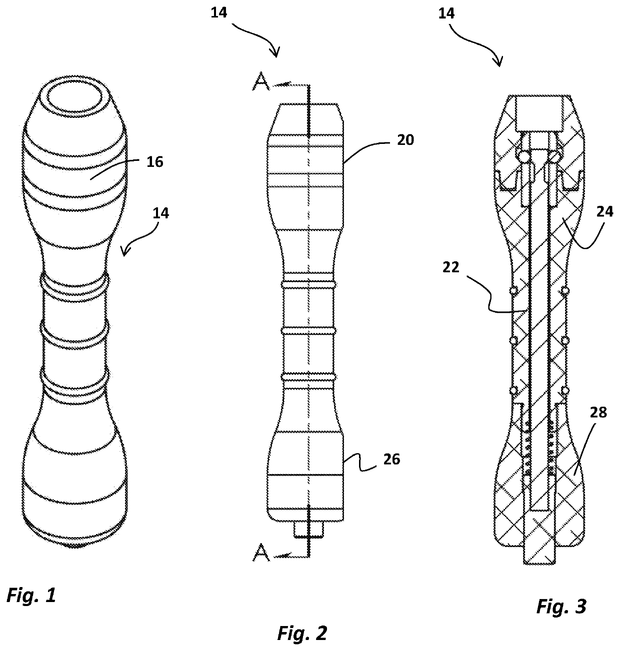
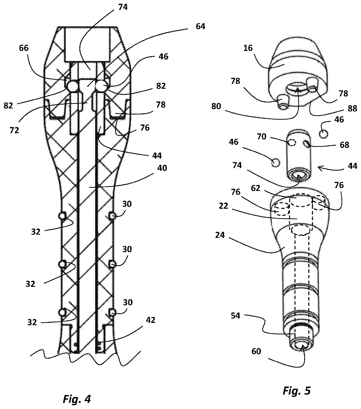
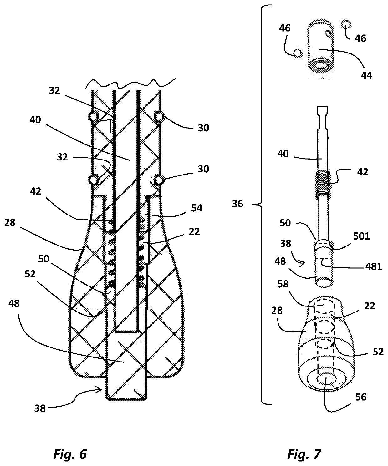
[0037]Referring to FIGS. 1-8, there is shown the hair brush 12 in accordance with preferred embodiments. As used herein, the terms “a” or “an” shall mean one or more than one. The term “plurality” shall mean two or more than two. The term “another” is defined as a second or more. The terms “including” and / or “having” are open ended (e.g., comprising). The term “or” as used herein is to be interpreted as inclusive or meaning any one or any combination. Therefore, “A. B or C” means “any of the following: A; B; C; A and B; A and C; B and C; A, B and C”. An exception to this definition will occur only when a combination of elements, functions, steps or acts are in some way inherently mutually exclusive.

[0038]Reference throughout this document to “one embodiment,”“certain embodiments,”“an embodiment,” or similar term means that a particular feature, structure, or characteristic described in connection with the embodiment is included in at least one embodiment of the present disclosure. T...


PUM


Abstract

The hair brush generally comprises a handle and a removably coupled brush head retainer. The brush head retainer is adapted to receive a variety of different hair brush heads comprising a variety of types of bristles. The handle comprises a centrally tapered configuration that is easily grasped by a user. Upper and lower portions define a central longitudinal passage. Axially aligned within this passage is a handle coupling assembly comprising an activation member, push rod, spring, barrel, and one or more ball bearings. The brush head retainer comprises a brush head retainer lower opening, an inner annular groove, and one or more lower pins. The inner annular groove comprises an angled lower portion which is transversely aligned with the barrel side openings. The push rod is moveable between first and second positions such that the brush head retainer may be coupled and decoupled.

Description

BACKGROUND OF THE INVENTION1. Field of the Invention[0001]The present invention relates generally to hair brushes adapted for use by salon stylists and specifically to a hair brush comprising a removable handle adapted to accept multiple types of hair brush heads and styling accessories.2. Description of the Prior Art[0002]Hair brushes have been known in the art since well before the beginning of the 19th century. Originally, hair brushes were a luxury item owned primarily by well-to-do individuals. In the United States, one of the first issued patents for a hair brush was U.S. Pat. No. D645 issued to Rock. Rock provided for a hair brush comprising an elliptical shape and a metallic frame handle. One of the first utility patents for a hair brush is U.S. Pat. No. 106,680 to Firey. Firey provides for a hair brush comprising wire teeth and bristles on one side of the brush and ordinary bristles on the other.[0003]Over the years, manufacturing techniques improved and hair brushes became...

Claims


Application Information

Patent Timeline
IPC IPC(8): A46B5/00A46B5/02
CPCA46B2200/104A46B5/02A46B7/04A46B5/021A46B5/0095
Inventor LANKFORD, HEATHERREYNA, JACQUELYNLOPEZ, LAMAR
Owner L & R PRO LLC
Why Eureka
Try Eureka