
Filtration mask, packaged filtration mask, and tearable container

Active Publication Date: 2019-11-07
AVON POLYMER PROD LTD
View PDF0 Cites 1 Cited by
  • Summary
  • Abstract
  • Description
  • Claims
  • Application Information

AI Technical Summary

Benefits of technology

The patent discusses how filtration masks are typically stored in a vacuum bag to protect them from contamination. However, the inventors have realized that sometimes the vacuum bag may get damaged, which may cause the vacuum to be lost and allow ambient gas to enter the bag. This could lead to the filtration mask becoming contaminated or degraded, which would need to be replaced to prevent issues when using them. The technical effect of this patent is to provide a solution to prevent damaged vacuum bags and ensure the filtration masks are always protected during storage.

Problems solved by technology

However, the present inventors have realised that during storage it is possible for the vacuum bag to become damaged, so that the vacuum or partial vacuum in the vacuum bag is lost and ambient gas enters the vacuum bag.
The present inventors have further realised that in some cases such damage may be very difficult, or impossible, to spot, such that it is not noticed that the vacuum or partial vacuum in the vacuum bag has been lost until the time that a person needs to use the filtration mask.
By this time, the filtration mask may already have been contaminated and / or degraded by the ambient gas, meaning that the user is not properly protected by the filtration mask.
For example, a small puncture of the vacuum bag will allow ambient gas into the vacuum bag and may not be easily visible upon visual inspection of the vacuum bag.

Method used


Image

  • Filtration mask, packaged filtration mask, and tearable container
  • Filtration mask, packaged filtration mask, and tearable container
  • Filtration mask, packaged filtration mask, and tearable container

Examples


first embodiment

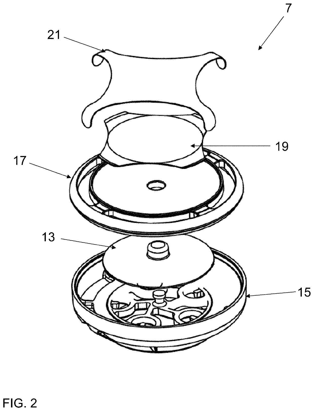
[0301]For example, in the first embodiment an indicator other than the tactile dome component can be used. For example, the indicator may have a different shape to a dome shape, and / or may move between two different positions instead of being compressed / depressed, and / or may be located in a different part of the filtration mask or container.

second embodiment

[0302]For example, in the second embodiment, the channel of the second part may have a different configuration. For example, the channel may comprise a portion where the thickness of the second part is reduced rather than omitting the second part, or where the resistance to tearing of the second part is otherwise reduced, for example by providing perforations in the second part. The tearable container may also or alternatively have a different configuration to the vacuum bag illustrated in FIGS. 6 and 7.

third embodiment

[0303]In the third embodiment, other shapes and / or configurations of non-planar surface can be used instead of the specific example of the non-planar surface illustrated in FIGS. 8 to 11.

[0304]Other aspects and / or embodiments of the present invention may be as specified in the following numbered clauses:

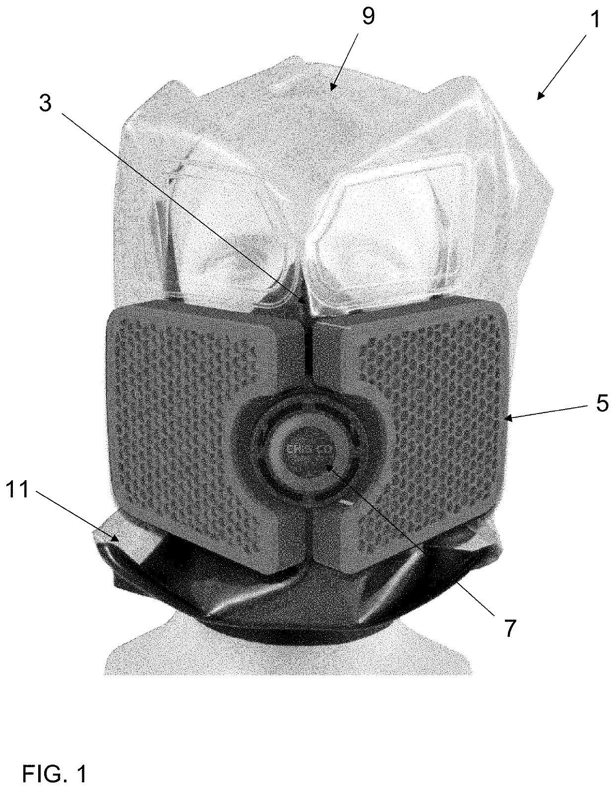
[0305]1. A packaged filtration mask comprising a filtration mask packaged in a container in a vacuum or a partial vacuum, wherein the packaged filtration mask comprises an indicator configured to indicate the presence of a vacuum or a partial vacuum in the container, or configured to indicate the lack of a vacuum or a partial vacuum in the container.

[0306]2. The packaged filtration mask according to clause 1, wherein the indicator is configured to adopt a first configuration when there is a vacuum or a partial vacuum in the container, and to adopt a second configuration when there is not a vacuum or a partial vacuum in the container.

[0307]3. The packaged filtration mask according to ...


PUM

PropertyMeasurementUnit
Forceaaaaaaaaaa
Flexibilityaaaaaaaaaa
Deformation enthalpyaaaaaaaaaa

Abstract

A packaged filtration mask comprising a filtration mask packaged in a container in a vacuum or a partial vacuum, wherein the packaged filtration mask comprises an indicator configured to indicate the presence of a vacuum or a partial vacuum in the container, or configured to indicate the lack of a vacuum or a partial vacuum in the container.

Description

CROSS-REFERENCE TO RELATED APPLICATIONS[0001]This patent application claims the benefit of UK patent application no. 1807377.5 filed on 4 May 2018, which is incorporated by reference herein.FIELD OF THE INVENTION[0002]The present invention relates to a filtration mask, such as an emergency hood, to a packaged filtration mask, and to a tearable container, which for example may be used to contain a filtration mask.BACKGROUND OF THE INVENTION[0003]Filtration masks are masks that filter ambient gas inhaled into the mask by a person wearing the mask, to produce filtered gas for breathing by the person wearing the mask. A filtration mask can therefore protect the person wearing the mask from inhaling harmful substances in the ambient gas.[0004]Filtration masks are well-known, and in general their configuration depends on their intended use, for example the type(s) of substance that they are intended to filter out, the intended length of time of use, or the environment in which they are in...

Claims


Application Information

Patent Timeline
IPC IPC(8): B65D79/00B65D81/20B65D75/58A62B18/02A62B23/02A62B18/08
CPCA62B23/025B65D81/2023B65D75/5805A62B18/02B65D79/005A62B18/08A62B9/006A62B27/00A62B25/00B65D2201/00B65D79/008B65D33/004
Inventor HUNTER, NICHOLAS JOHNSMITH, PHILIP ADAM
Owner AVON POLYMER PROD LTD
Learn More