
Connector For A Surgical Lighting System

a technology of surgical lighting and connectors, applied in the field of surgical lighting systems, can solve the problems of inability to use, metal casings can also present problems, and conventional light carriers are not versatil

Active Publication Date: 2019-11-07
SUNOPTIC TECH
View PDF0 Cites 0 Cited by
  • Summary
  • Abstract
  • Description
  • Claims
  • Application Information

AI Technical Summary

Benefits of technology

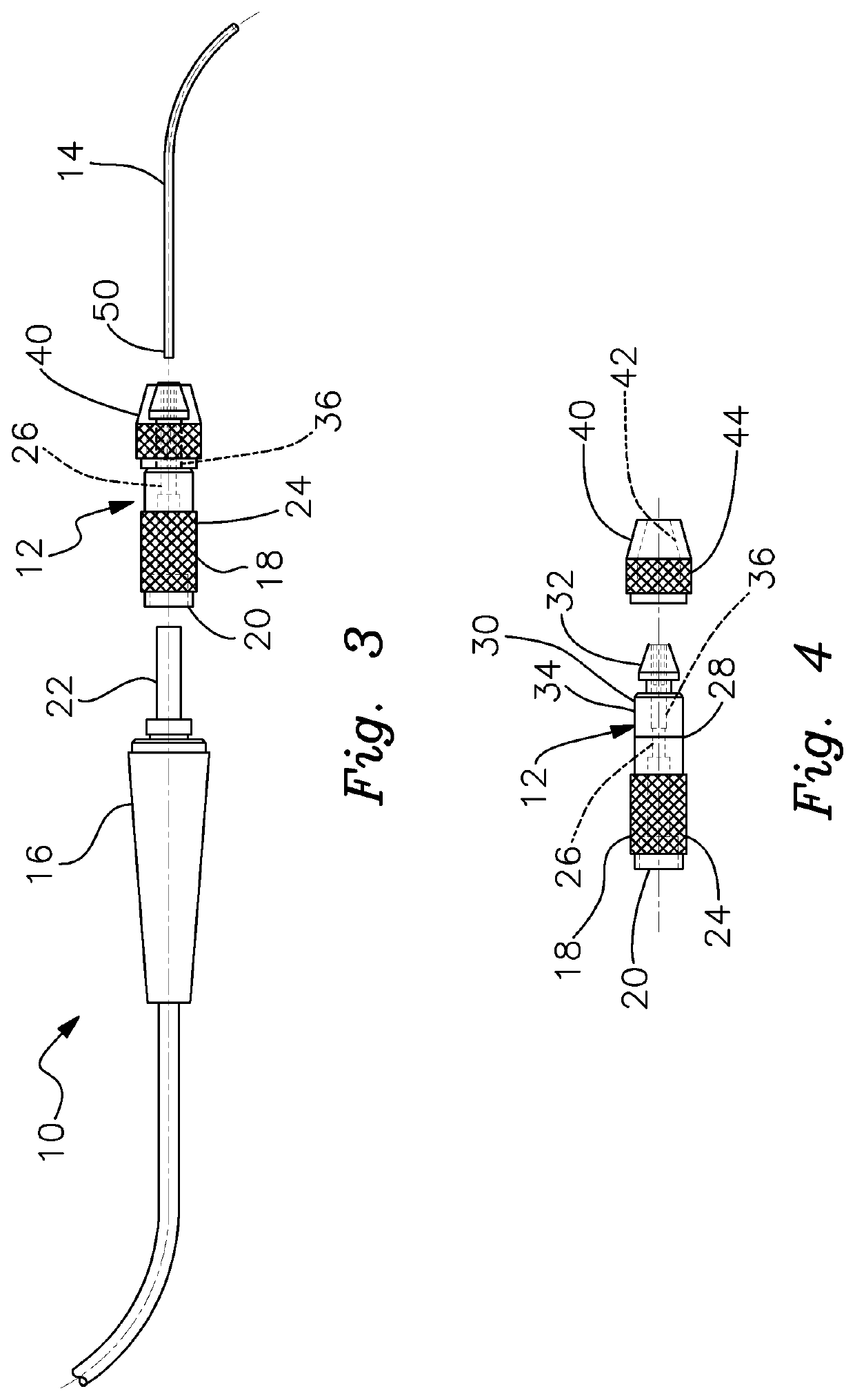
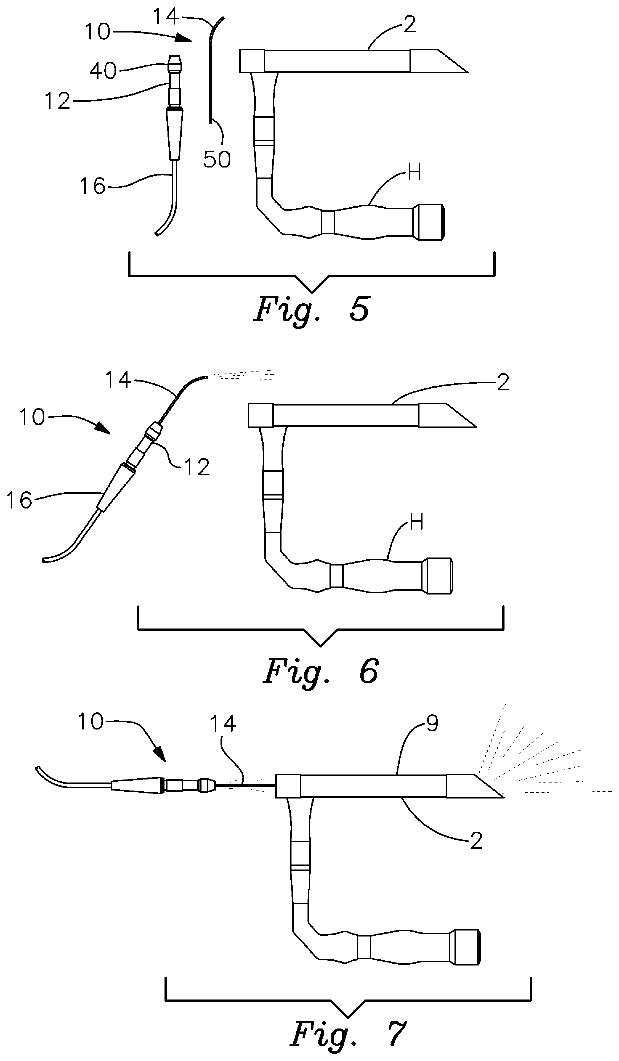
The present invention is a surgical lighting system that is versatile and can be used with various types and sizes of scopes and instruments. It features a unique gripping connector that allows for interchangeable use of fiberoptic light carriers. This system reduces the expense and inconvenience of maintaining a large inventory of lighting systems with different sizes and configurations.

Problems solved by technology

Because the light carrier is secured within a rigid metal casing, its use is normally limited to only a single type of scope, as well as a scope that has a specific corresponding size and configuration.
Conventional light carriers are not versatile and cannot be used with the wide variety of medical and surgical scopes that are currently available.
The metal casing can also present problems because, during use, it is apt to transmit heat generated by the light carrier.
This can make the scope difficult to handle, which is likely to interfere with or complicate the surgical or medical procedure being performed.
Scopes featuring the known light carrier can also be difficult to clean and sanitize.
This can cause the build up of contaminants which can be troublesome to remove.

Method used


Image

  • Connector For A Surgical Lighting System
  • Connector For A Surgical Lighting System
  • Connector For A Surgical Lighting System

Examples


Embodiment Construction

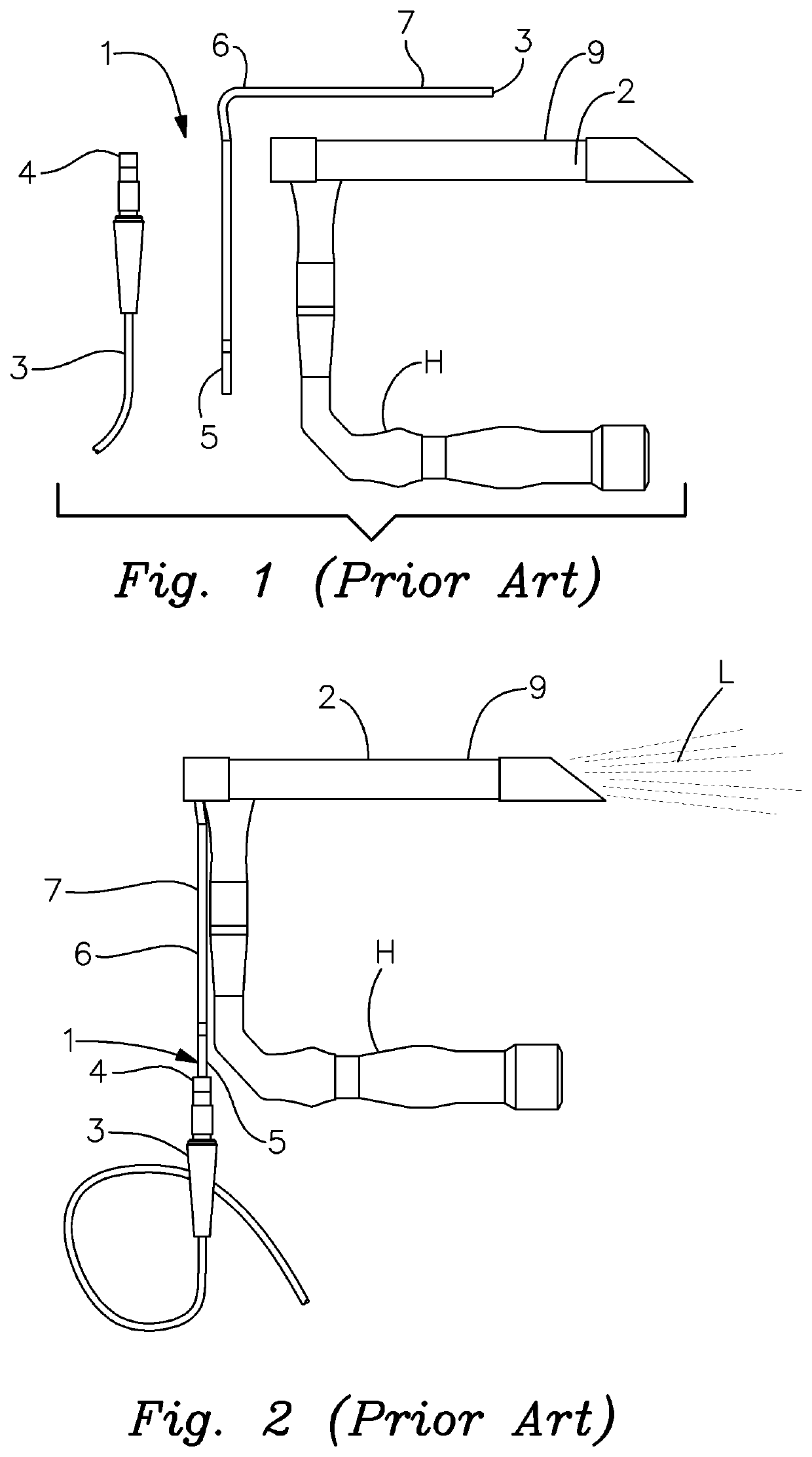
[0027]There is shown in FIGS. 1 and 2 a surgical lighting system of the type conventionally employed for medical instruments. Such instruments typically comprise scopes designed to illuminate various sorts of medical procedures. These can include, but are not limited to laryngoscopes, laparoscopes, ENT scopes and endoscopes. It should be understood that the type of scope or medical instrument with which the invention may be employed is not a limitation of this invention.

[0028]FIGS. 1 and 2 depict a conventional lighting system 1 as used with a representative laryngoscope 2. Lighting system 1 features a standard fiberoptic cable 3 that is operatively connected in a known manner at an inlet end (not shown) to a fiberoptic illuminator or other light source, which will be well known to persons skilled in the art. A standard light discharge or outlet fitting 4 of cable 3 is communicably connected to an inlet end 5 of a generally L-shaped light conducting component 6. As is known in the p...


PUM


Abstract

A surgical lighting system includes a connector for communicably joining a light carrier to a fiberoptic cable. The connector includes an inlet section having a receptacle for operatively engaging a light discharge outlet of the fiberoptic cable. A chuck mechanism includes a body that is rotatably interconnected with the inlet section. The chuck body has a passageway that communicates with the outlet of the fiberoptic cable engaged with the receptacle of the inlet section. The chuck mechanism also includes a set of adjustable jaws that are selectively opened and closed by turning a cap attached to the chuck body. Opening the jaws exposes the passageway through the chuck mechanism. The light carrier is engaged with the exposed passageway and the jaws are closed to grip the light carrier and communicably connect the fiberoptic cable to the light carrier.

Description

FIELD OF THE INVENTION[0001]This invention relates to a surgical lighting system employed to illuminate various medical and surgical procedures. More particularly, the invention relates to a connector for releasably securing an illuminating light carrier to a standard fiberoptic cable.BACKGROUND OF THE INVENTION[0002]Various types of lighting systems are currently available for use with lighted medical and surgical scopes including, for example, ENT scopes, laparoscopes, endoscopes, etc. Typically, in such lighting systems, the light inlet of a standard fiberoptic cable is connected to an illuminator or other type of light source. The opposite, outlet end of the fiberoptic cable is attached to a standard rigid glass fiber light carrier, which is itself encased and fused within an elongate metal sleeve or tube. This sleeve is sized and configured to fit snugly in a channel of the scope that is being utilized. Light is directed from a distal output end of the light carrier and dischar...

Claims


Application Information

Patent Timeline
Patent Type & Authority Applications(United States)
IPC IPC(8): A61B90/30A61B90/50F21V33/00
CPCF21W2131/205A61B2090/306A61B17/00234A61B90/30A61B2017/0023A61B90/50F21V33/0068
Inventor MARSH, KIM A.
Owner SUNOPTIC TECH
Learn More