
Clock using bright dot display

a bright dot display and clock technology, applied in the field of clocks using bright dot displays, can solve the problems of difficult to improve the aesthetic design of the numeric representation, the frame restricts its aesthetic design, and the movement of the hands makes noises, etc., to achieve the effect of breaking the monotony of the clock design and being easy to read

Inactive Publication Date: 2019-10-24
HO KUEI CHUAN +1
View PDF3 Cites 3 Cited by
  • Summary
  • Abstract
  • Description
  • Claims
  • Application Information

AI Technical Summary

Benefits of technology

The present invention aims to provide a clock that uses bright dot display to indicate time, which is easy to read and visually appealing to break the monotony of clock design. The clock comprises illuminating display units arranged for the graduated marks of the clock and a micro processing unit that causes the illuminating display units to illuminate according to the time calculated by a time base unit. Each illuminating display unit has three states - "hour indicator mark," "minute indicator mark," and both at once. The user can easily read the time by observing the on and off states of the illumination of the markers and the colors of the illuminating display units.

Problems solved by technology

1. Its need to be framed restricts its aesthetic design.
2. As its hands are driven by a mechanism, the movement of the hands makes noises, which may be particularly loud at quiet night.
3. Lighting is needed when one needs to check the time at night.
Although the digital clock does not have the foregoing disadvantages of the analog clock, it is still hard to improve the aesthetic design of its numeric representation.
Further, the functions of the variety of clocks are mostly limited to displaying time and providing decoration with its aesthetic design.
They are monotonous and lackluster.
Further, clocks may be disposed on some outdoor billboards or shop signs, but again these clocks are monotonous and lackluster.

Method used


Image

  • Clock using bright dot display
  • Clock using bright dot display
  • Clock using bright dot display

Examples


Embodiment Construction

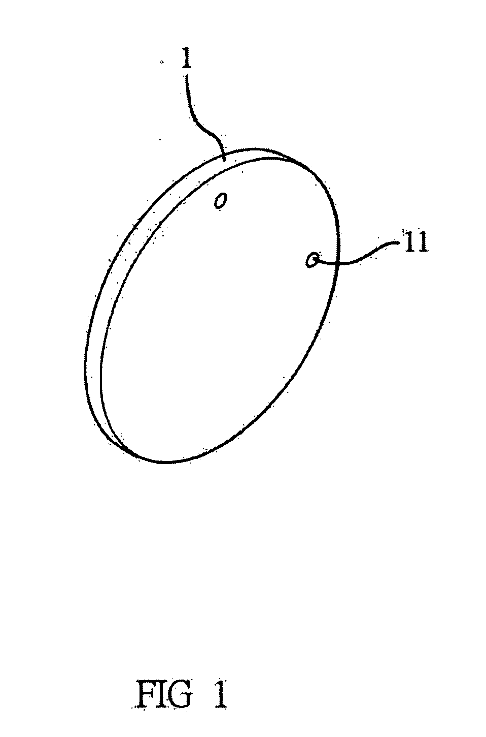
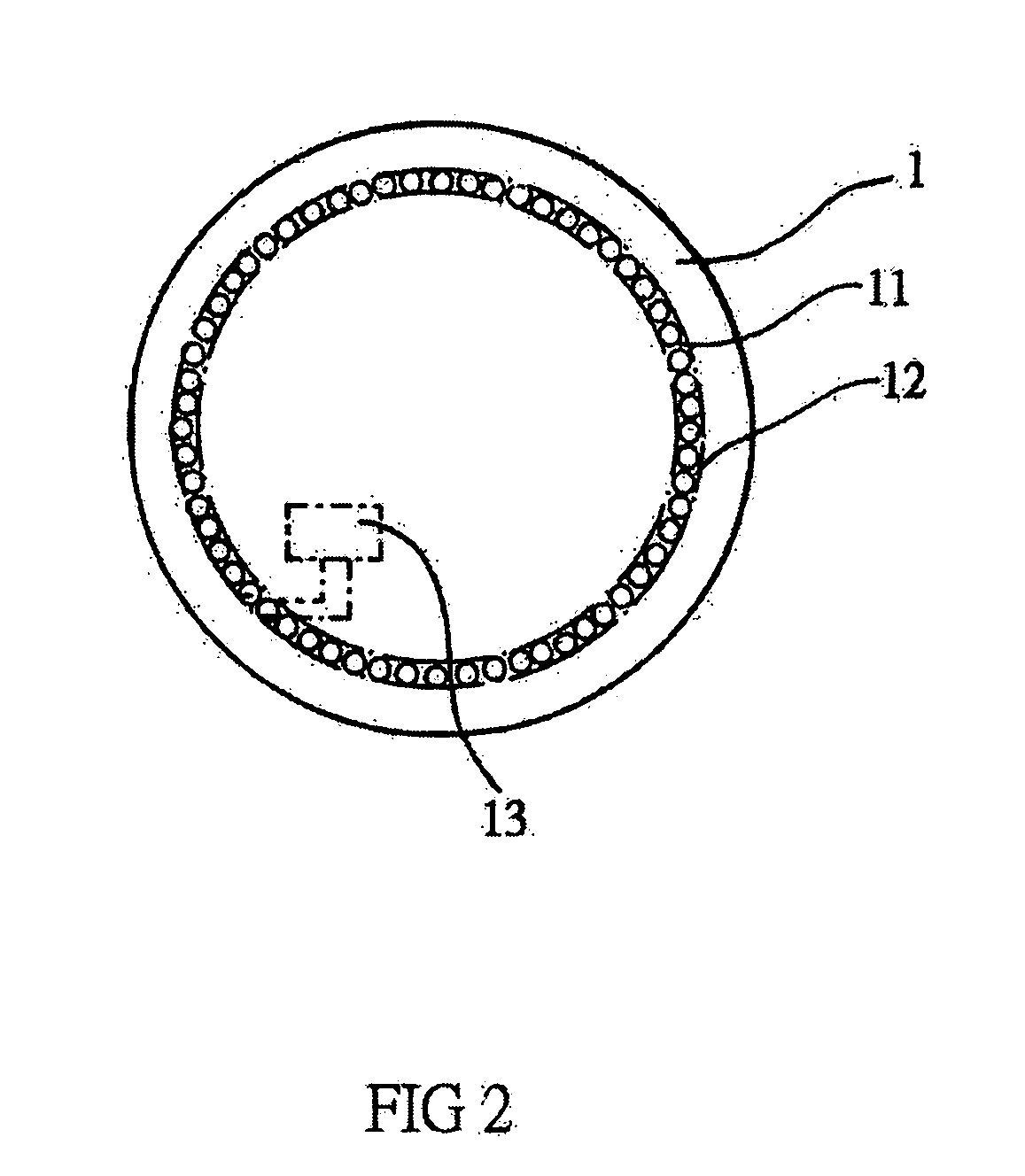
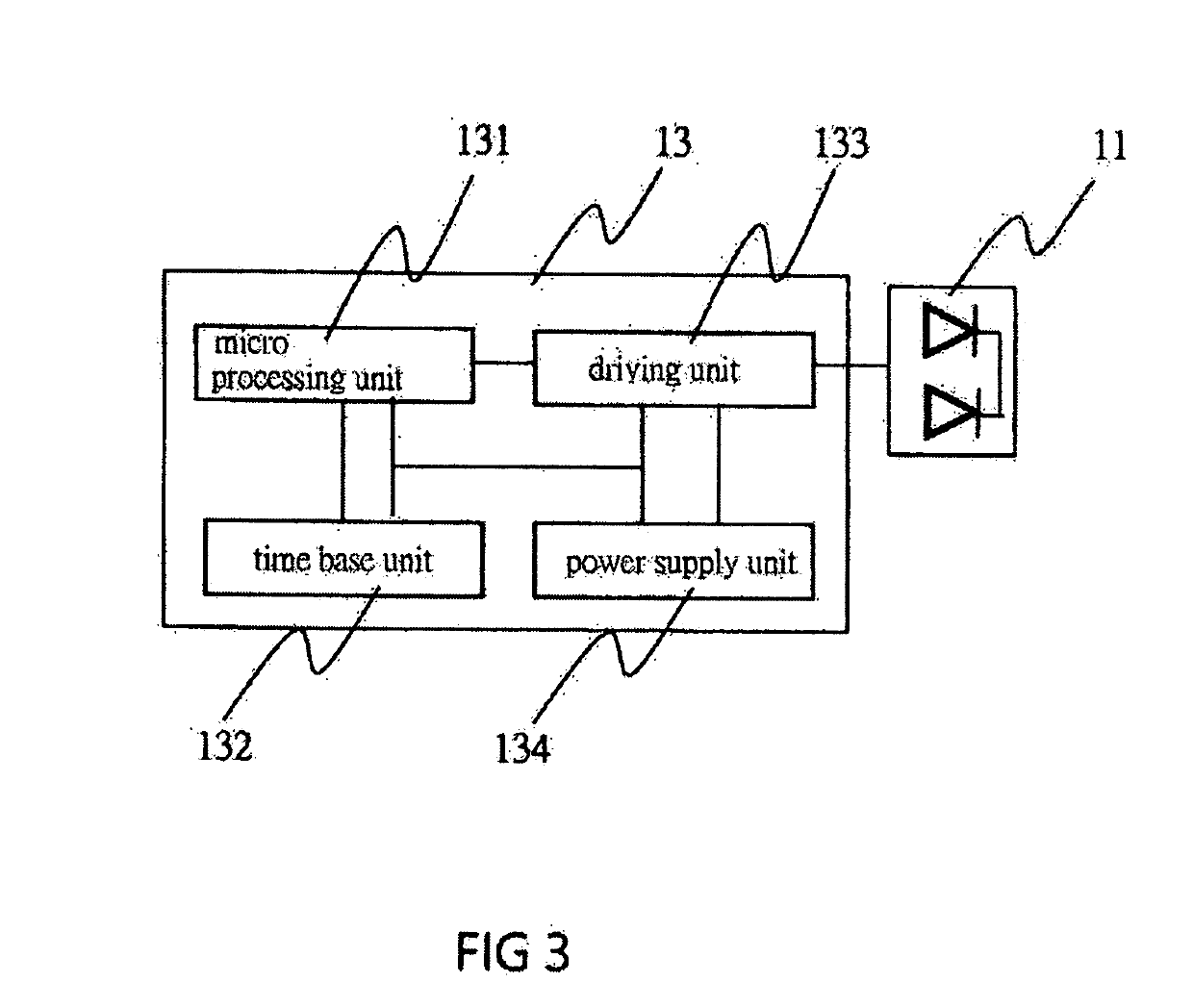
[0021]Please refer to FIG. 1 and FIG. 2 as well as FIG. 3, showing respectively a three-dimensional view and a structural drawing of the present invention, and a block diagram of a circuit according to a preferred embodiment of the present invention. As the figures show, the present invention comprises spaced illuminating display units 11 arranged for the graduation marks on a main body 1 of the clock. Each of the illuminating display units 11 includes a first illuminating state, a second illuminating state and a third illuminating state, and the illuminating display units 11 are spaced according to the graduations of the clock. In this preferred embodiment, there are 60 illuminating display units 11 for the “hours” and the “minutes.” The illuminating display unit 11 is the “hour indicator mark” in its first illuminating state, the “minute indicator mark” in its second illuminating state, and both the “hour indicator mark” and “minute indicator mark” in its third illuminating state....


PUM


Abstract

A clock using bright dot display comprises spaced illuminating display units arranged for the graduation marks of the clock, a micro processing unit which causes the illuminating display units of corresponding graduation marks to illuminate according to the time calculated by a time base unit. Each of the illuminating display units includes a first illuminating state, a second illuminating state and a third illuminating state. The illuminating display unit is the “hour indicator mark” in its first illuminating state, the “minute indicator mark” in its second illuminating state, and both the “hour indicator mark” and “minute indicator mark” in its third illuminating state. A user may easily read the time by observing the on and off states of the illumination of the “hour indicator mark” and “minute indicator mark” as well as the illumination colors of the illuminating display units.

Description

BACKGROUND OF THE INVENTION1. Field of the Invention[0001]The present invention relates to a clock using bright dot display and particularly to a clock using bright dot display which indicates time using easily readable indicator marks without making noises like a conventional analog clock with moving hands.2. Description of Related Art[0002]There are two types of conventional clocks, the analog clock and the digital clock. The analog clock typically comprises a main body, an hour hand and a minute hand, wherein time is indicated using graduation marks on the main body. This type of clock has the following disadvantages:[0003]1. Its need to be framed restricts its aesthetic design.[0004]2. As its hands are driven by a mechanism, the movement of the hands makes noises, which may be particularly loud at quiet night.[0005]3. Lighting is needed when one needs to check the time at night.[0006]The digital clock, on the other hand, displays time on a display panel. Although the digital clo...

Claims


Application Information

Patent Timeline
IPC IPC(8): G04G9/04G09G3/12
CPCG09G3/12G04G9/04G09G3/14
Inventor CHEN, WEN-CHIN
Owner HO KUEI CHUAN
Learn More