Eureka AIR delivers breakthrough ideas for toughest innovation challenges, trusted by R&D personnel around the world.

Apparatus for injection molding of plastic materials

Inactive Publication Date: 2019-10-17
INGLASS SPA
View PDF29 Cites 0 Cited by
  • Summary
  • Abstract
  • Description
  • Claims
  • Application Information

AI Technical Summary

Benefits of technology

The invention aims to improve the cooling of the actuator in plastic injection molding machines. It introduces an apparatus that allows for more efficient and effective cooling through the use of air flow. This results in improved manufacturing efficiency and quality.

Problems solved by technology

The use of such elastic members entails construction complications and the thermal exchange between the jack and the plate made available by such elastic members is generally limited and thus scarcely efficient.
These solutions are however scarcely efficient.

Method used


Image

  • Apparatus for injection molding of plastic materials
  • Apparatus for injection molding of plastic materials

Examples


Embodiment Construction

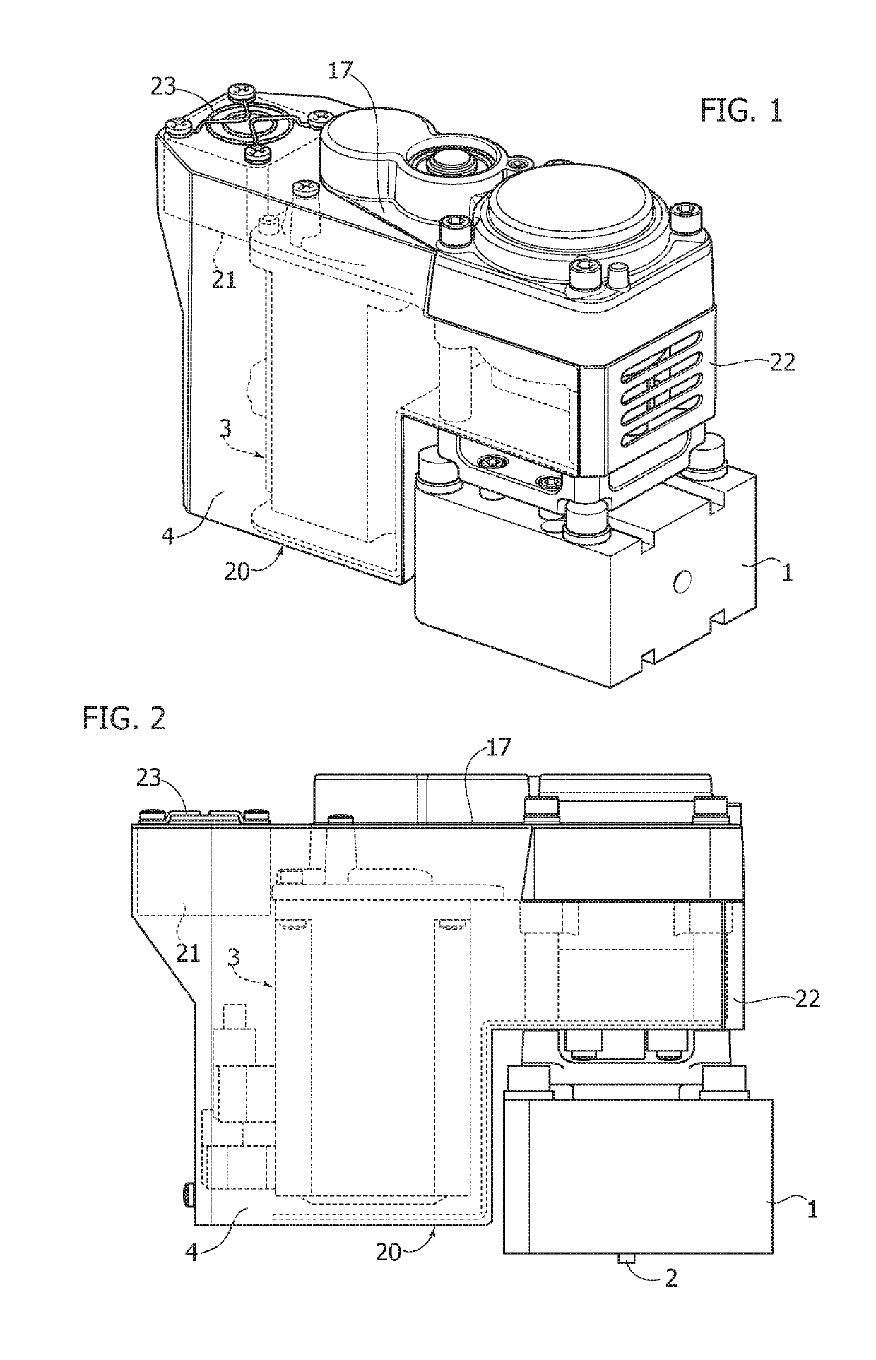
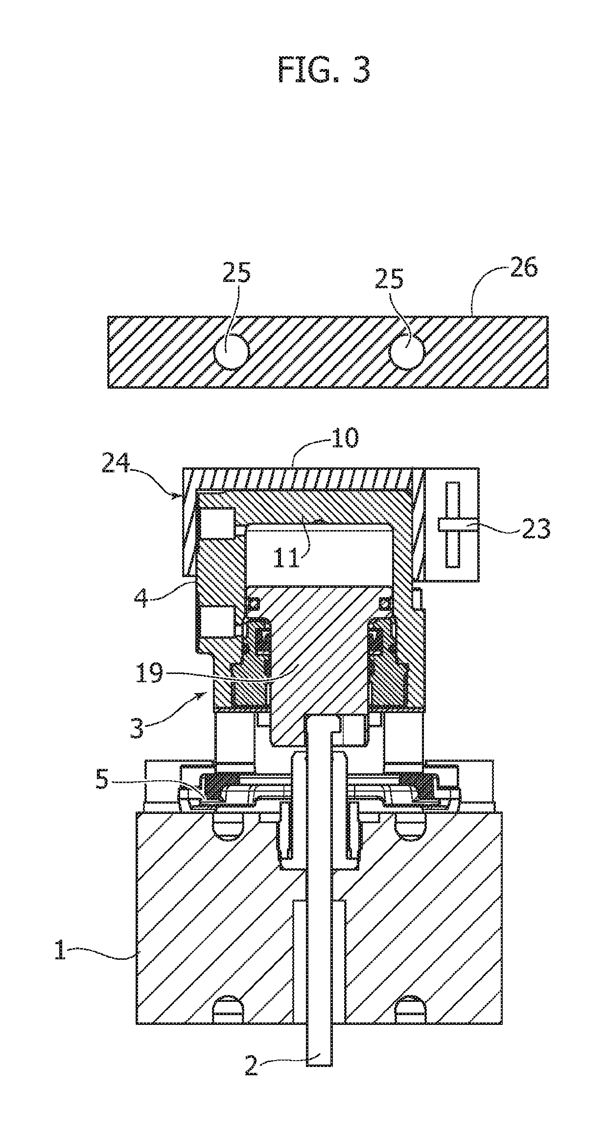
[0018]An apparatus for injection molding of plastic materials conventionally comprises a press (not illustrated) for sending the fluid plastic material to a distributor or hot runner 1 from which the plastic material is injected into the mold cavity (not illustrated) through one or more injectors. Each injector comprises a valve pin 2 displaceable, relatively to a mold gate, between a full closing position and a maximum opening position. The displacement of the valve pin 2, and thus the opening and closing of the injector, is carried out by an actuator which, in the case of the present invention, consists of a jack indicated in its entirety with 3, pneumatic or hydraulic or electric.

[0019]In the case of the example described herein with reference to FIGS. 1 and 2, the jack 3 consists of an electric actuator and it comprises a cylinder or body 4 which is supported by distributor 1 indirectly, adjacent to the latter. In the case of FIG. 3 the jack 3 is of the fluid type and it include...


PUM

PropertyMeasurementUnit
Flow rateaaaaaaaaaa
Electric propertiesaaaaaaaaaa
Thermal insulatoraaaaaaaaaa

Abstract

An apparatus for injection molding of fluid plastic materials includes a mold, a hot runner distributor of the fluid plastic material, at least one injector, and an actuator for controlling the opening and closing of the injector, including a jack whose cooling is performed by means of an air flow.

Description

FIELD OF THE INVENTION[0001]The present invention refers to apparatus for injection molding of plastic materials of the type comprising a mold, a hot runner distributor of the fluid plastic material, at least one injector for the introduction of the plastic material from the distributor into the mold cavity, and an actuator for controlling the opening and closing of the injector.[0002]More in particular, the invention refers to molding apparatus thus made wherein the actuator which actuates the injector, typically provided with a valve pin axially displaceable between a full closing position and a maximum opening position of the injector, consists of a jack normally supported by the distributor.STATE OF THE PRIOR ART[0003]During the operation of the molding apparatus, the jack, whether pneumatic or hydraulic or electric, is subjected to heating by means of the heat of the distributor, and it is conventionally cooled by means of an autonomous cooling hydraulic circuit. In some applic...

Claims


Application Information

Patent Timeline
IPC IPC(8): B29C45/28B29C45/72B29C45/23
CPCB29C2045/1792B29C45/281B29C2045/7271B29C45/72B29C45/231B29C45/28B29C45/7337
Inventor VILLA, RICCARDOTREVISIOL, NICO
Owner INGLASS SPA
Why Eureka
Eureka Blog
Learn More