Sample detection device

a detection device and sample technology, applied in the field of sample detection devices, can solve the problems of on-going running costs, and the interpretation of data produced can also prove challenging

Active Publication Date: 2019-09-12
UNIVERSITY OF ST ANDREWS
View PDF14 Cites 0 Cited by
  • Summary
  • Abstract
  • Description
  • Claims
  • Application Information

AI Technical Summary

Benefits of technology

[0068]Advantageously, the method may allow a user to determine not only the presence of infectious microorganisms in a...

Problems solved by technology

Safe operation also requires a regular input of reagents and this contributes to...

Method used


Image

  • Sample detection device
  • Sample detection device
  • Sample detection device

Examples


Embodiment Construction

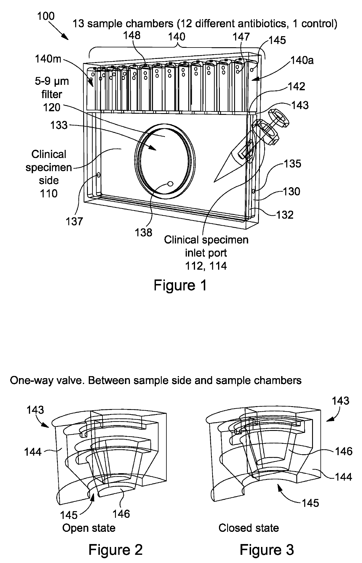
[0080]Referring to FIG. 1 there is shown a perspective wireframe view of a cartridge, generally designated 100, according to an embodiment of the present invention.

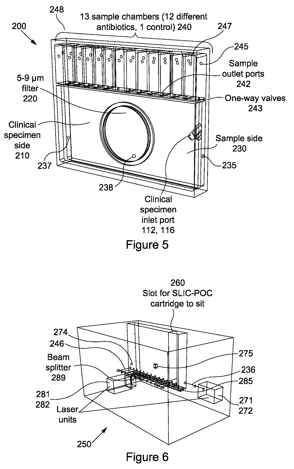
[0081]The cartridge 100 has a specimen chamber 110 configured to receive a sample, in this embodiment a clinical sample such as blood, urine, cerebrospinal fluid (CSF), pus, joint aspirate, another bodily fluid, or the like. The cartridge 100 has a sample feed arrangement 112 to allow a user to feed the clinical sample into the specimen chamber 110. In this embodiment, the sample feed arrangement 112 is a Luer lock type arrangement 114. However, any other type of feeding arrangement may be envisaged which permits effective delivery of the sample into the specimen chamber 110, for example the alternative arrangement as shown in FIG. 5.

[0082]The cartridge 100 has a semipermeable membrane 120 which allows passage of microorganisms from the specimen chamber 110 into a first detection chamber 130.

[0083]In this embodiment, the ...


PUM


Abstract

An apparatus (150) comprises a first detection chamber (130) for receiving microorganisms and configured to allow detection of the microorganisms via detection of scattered light from the first detection chamber (130); a medium (120) configured to permit passage of microorganisms from a sample (110) through the medium (120) into the first detection chamber (130); and at least one second detection chamber (140) configured to allow detection of the microorganisms via detection of scattered light from the at least one second detection chamber (140).

Description

[0001]The present invention relates to apparatuses and methods for measuring at least one characteristic of a sample, and in particular, though not exclusively, for measuring the presence and / or the growth of microorganisms in a biological sample, using light.BACKGROUND OF THE INVENTION[0002]Classic spectrophotometers can be used to determine optical properties of bacteria using absorption or scattering. Absorption spectrophotometers can be used to measure the relative absorbance of a sample. Absorbance is measured by comparing the intensity of light entering a sample with the intensity of light exiting the sample. A drop in light intensity indicates a quantity of light has been absorbed. This can be displayed as an arbitrary figure, typically an optical density. This can lead to an accurate count of the number of cells present in a sample.[0003]Scattering spectrophotometers usually comprise an intense light source, such as a laser or a very bright incandescent source, and a monochr...

Claims


Application Information

Patent Timeline
IPC IPC(8): G01N21/51B01L3/00C12Q1/04
CPCG01N2015/0693B01L2300/0864G01N2021/513B01L2200/027B01L2300/0854C12Q1/04B01L2300/0681B01L3/5027G01N21/51G01N2015/0065B01L2300/168B01L2300/0874G01N2021/4726B01L3/502B01L2200/026G01N15/06G01N21/11
Inventor HAMMOND, ROBERT J.H.GILLESPIE, STEPHEN H.
Owner UNIVERSITY OF ST ANDREWS
Why Eureka
Try Eureka