
Probe card device and rectangular probe

Active Publication Date: 2019-07-25
CHUNGHWA PRECISION TEST TECH
View PDF7 Cites 1 Cited by
  • Summary
  • Abstract
  • Description
  • Claims
  • Application Information

AI Technical Summary

Benefits of technology

The present invention is a probe card device with a rectangular probe that improves upon conventional rectangular probes and probe card devices. The new design has a metallic pin, insulating film, and insulating latch that prevent damage to the metallic pin while improving its ability to buffer against collision and friction with the upper and lower dies. Additionally, the new design secures the probe firmly to the dies, overcoming a common issue in conventional designs.

Problems solved by technology

However, the conventional rectangular probe is made of a single material, so that the conventional rectangular probe cannot be formed with a better current conduction property and a better mechanical strength property at the same time.
Moreover, when the rectangular probes are installed to the conventional probe card device or are used to test an object to be tested, some drawbacks (e.g., a collision, a great friction, or a poor fixation) easily occur between the rectangular probes and a probe head of the conventional probe card device.

Method used


Image

  • Probe card device and rectangular probe
  • Probe card device and rectangular probe
  • Probe card device and rectangular probe

Examples


Embodiment Construction

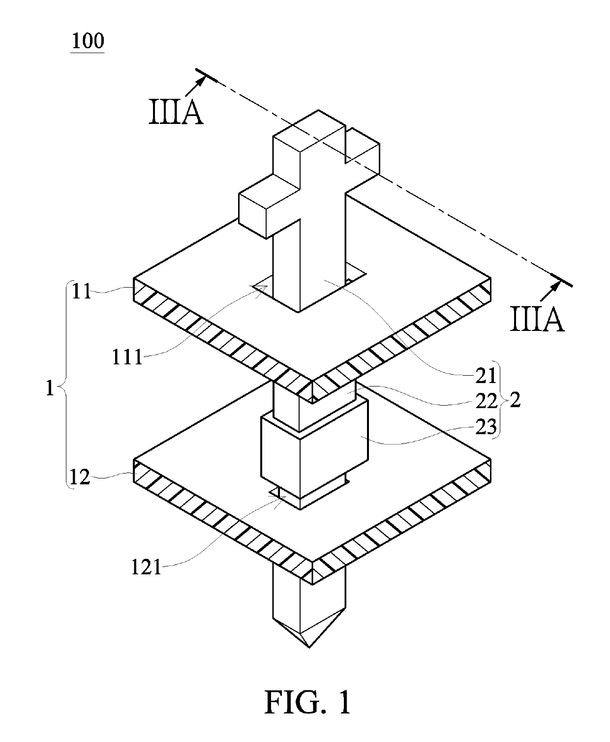
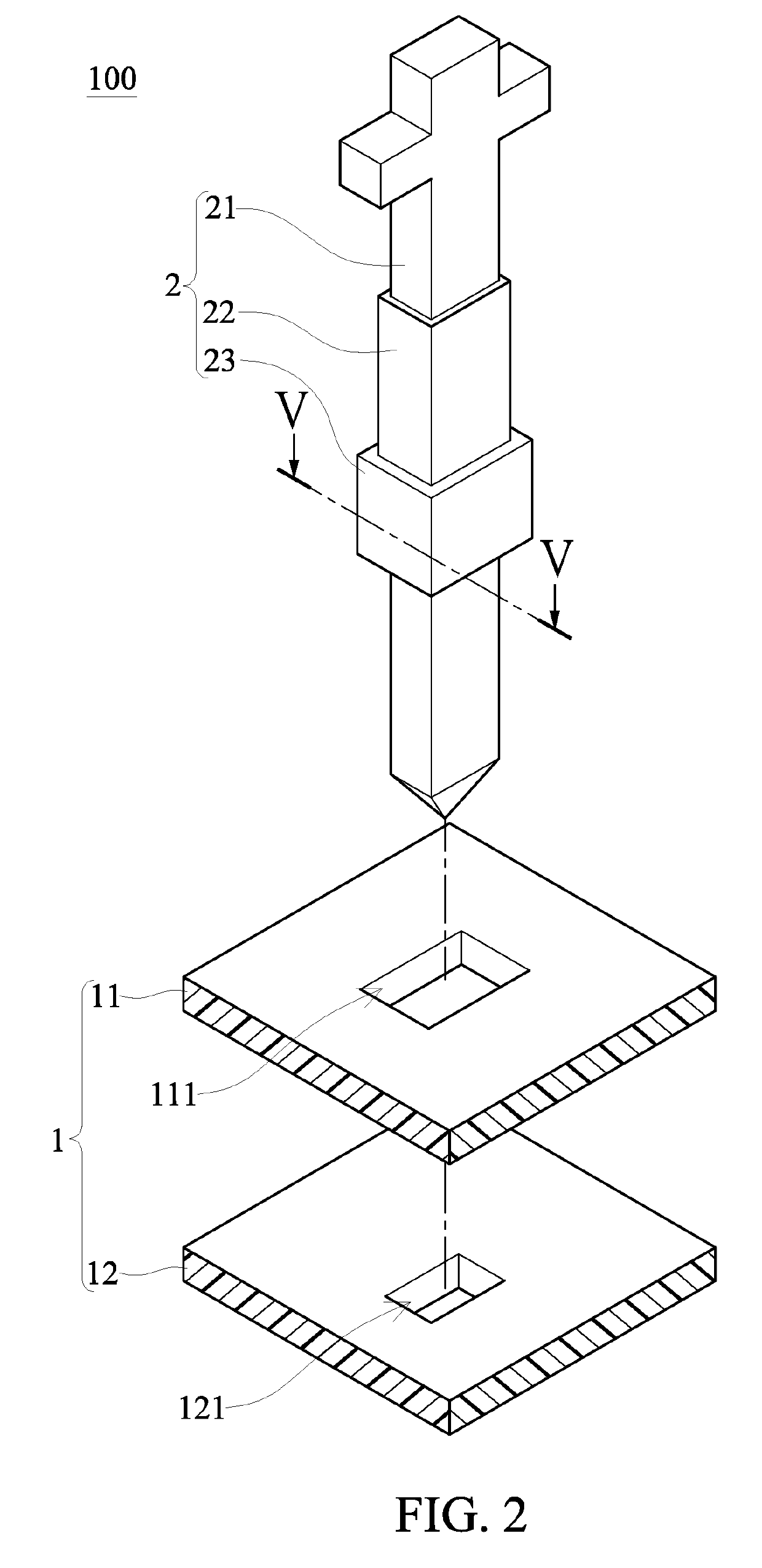
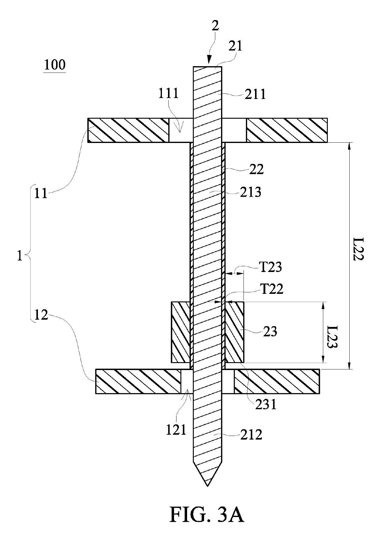
[0018]Reference is made to FIGS. 1 to 7, which illustrate an embodiment of the present disclosure. References are hereunder made to the detailed descriptions and appended drawings in connection with the present disclosure. However, the appended drawings are merely provided for exemplary purposes, and should not be construed as restricting the scope of the present disclosure.

[0019]As shown in FIGS. 1 and 2, the present embodiment discloses a probe card device 100. The probe card device 100 includes a probe head 1 and a plurality of rectangular probes 2 inserted into the probe head 1. Each of the rectangular probes 2 has a first end and a second end opposite to the first end. The first ends of the rectangular probes 2 respectively contact with a plurality of electrical pads of a space transformer (not shown), and the second ends of the rectangular probes 2 can be used for testing an object to be tested, such as a semi-conductor wafer (not shown).

[0020]In order to easily express the pr...


PUM


Abstract

The present disclosure discloses a probe card device and a rectangular probe. The rectangular probe includes a metallic pin, an insulating film, and an insulating latch. The metallic pin includes a connecting portion, a detecting portion, and a middle segment arranged between the connecting portion and the detecting portion. The insulating film covers entirely outer surfaces of the middle segment. The insulating latch is in a ring shape and is arranged around at least part of the insulating film. A bottom of the insulating latch is arranged adjacent to the detecting portion. A length of the insulating latch is less than or equal to that of the insulating film, and a thickness of the insulating latch is larger than that of the insulating film and is at least 10 μm.

Description

BACKGROUND OF THE INVENTION1. Field of the Invention[0001]The present disclosure relates to a probe card; in particular, to a probe card device and a rectangular probe.2. Description of Related Art[0002]In a testing process of semi-conductor wafer, a testing apparatus is electrically connected to an object to be tested by using a probe card device, and the testing apparatus can obtain a testing result of the object to be tested by signal transmission and signal analysis. The conventional probe card device has a plurality of probes corresponding in position to electrical pads of the object, and the probes are used to simultaneously and respectively contact with the electrical pads of the object.[0003]Specifically, the probes of the conventional probe card device can be rectangular probes, which can be made by using a microelectromechanical systems (MEMS) technology to form a determined shape according to design requirements. However, the conventional rectangular probe is made of a si...

Claims


Application Information

Patent Timeline
IPC IPC(8): G01R1/073G01R31/26
CPCG01R1/07307G01R31/2601G01R1/0735G01R1/07314G01R1/07371
Inventor HSIEH, CHIH-PENGCHEN, YEN-CHENSU, WEI-JHIH
Owner CHUNGHWA PRECISION TEST TECH
Learn More