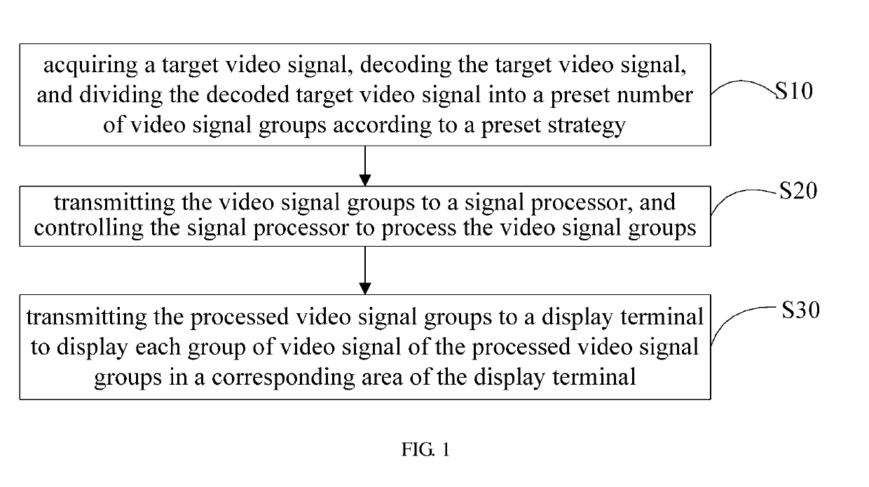
Video signal transmission method and device
a video signal and transmission method technology, applied in the field of video signal transmission, can solve the problems of image details lost in video and images cannot be truly restored, and achieve the effect of clear and smooth display of images and excellent viewing experien
- Summary
- Abstract
- Description
- Claims
- Application Information
AI Technical Summary
Benefits of technology
Problems solved by technology
Method used
Image
Examples
first embodiment
[0069]Referring to FIG. 5, FIG. 5 is a detailed flowchart of operation S20 in FIG. 1 according to the
[0070]In this embodiment, operation S20 includes:
[0071]Operation S201, transmitting the video signal groups to a signal processor,
[0072]Operation S202, enabling a preset transmission format conversion chip to convert the existing transmission format of the video signal groups into a preset transmission format.
[0073]In this embodiment, when the signal processor inputs a signal through HDMI line, the video signal transmission format is HDMI. Since the input interface of 8K television is commonly V-BY-ONE, the output interface of the signal processor is V-BY-ONE, and the transmission format of the signal needs to be converted into a transmission format conforming to V-BY-ONE. In this embodiment, the transmission format conversion chip is not restricted, it can be chosen according to actual needs, for example, MN 869121 may be used. The chip can convert HDMI video signal into video signa...
second embodiment
[0075]Referring to FIG. 6, FIG. 6 is a detailed flowchart of operation S20 in FIG. 1 according to the
[0076]In this embodiment, after operation S202, the method includes:
[0077]S203, determining the type of display, and judging whether motion compensation processing is required for the video signal groups according to the display type.
[0078]In this embodiment, the type of display mainly refers to the type of 8K television liquid crystal panel. For example, some are 8 k 60 fps liquid crystal panels and some are 8 k 120 fps liquid crystal panels. Perform motion compensation processing on the video signal groups, the motion compensation process is completed by the MEMC motion compensation processing chip. There is no restriction on the selection of MEMC motion compensation processing chip. According to actual needs, for example, NT 72334 TBG is selected for the process. For example, the original video signal is 8 k 60 fps, and the display screen is an 8 k 60 fps liquid crystal panel, und...
third embodiment
[0080]Referring to FIG. 7, FIG. 7 is a detailed flowchart of operation S20 in FIG. 1 according to the
[0081]In this embodiment, after operation S203, the method includes:
[0082]Operation S204, when motion compensation processing is required for the video signal group, enabling the preset MEMC motion compensation chip to perform motion compensation processing on the video signal groups.
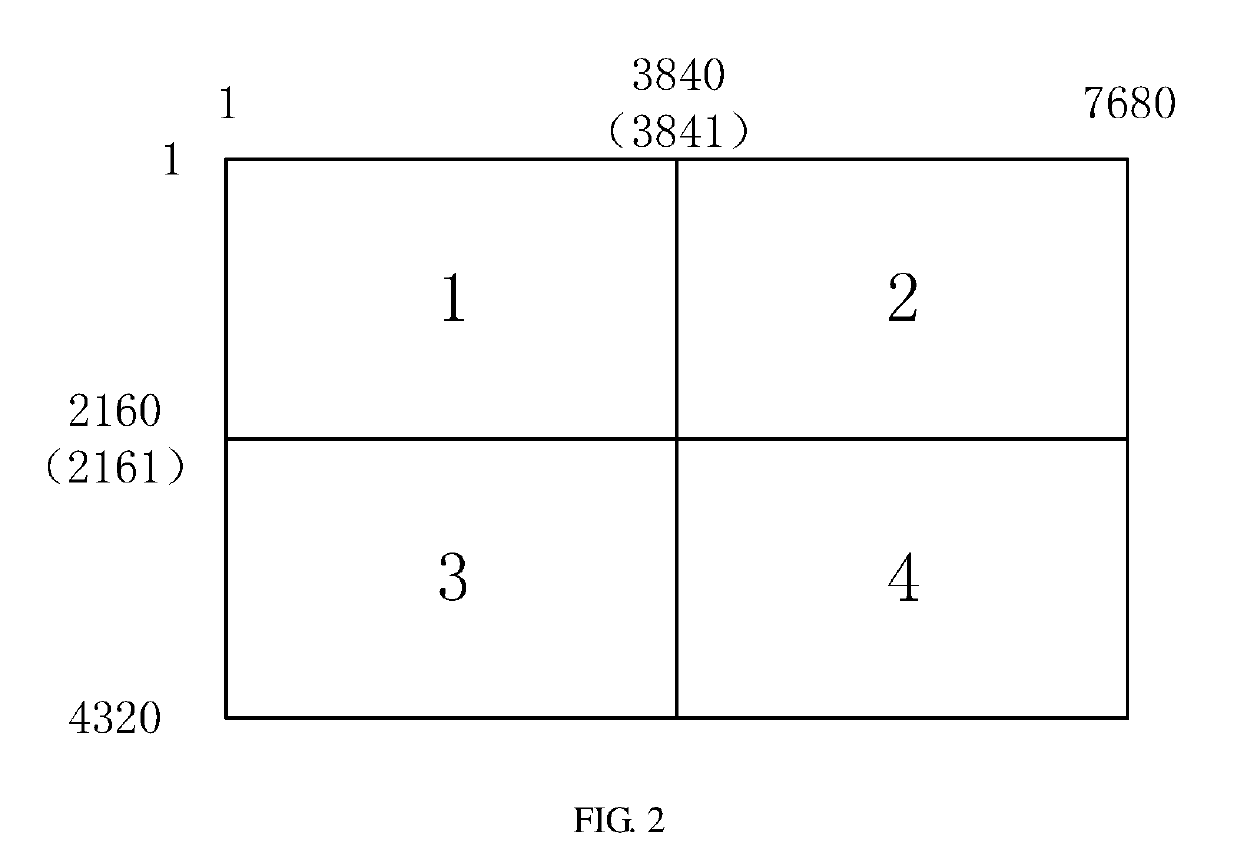
[0083]In this embodiment, when it is necessary to perform motion compensation processing on the video signal group, enabling the preset MEMC motion compensation chip to perform motion compensation processing on the video signal groups. For example, when the video signal group is 8 k 60 fps video signal, it is necessary to output the video signal to the 8 k 120 fps liquid crystal panel. Under this situation, convert 8K 60 fps video signal into 8K 120 fps video signal via the selected NT 72334 TBG motion compensation processing chip, and then output to the corresponding four blocks of the 8K 120 FPS televi...
PUM
 Abstract
Description
Claims
Application Information
 - R&D
- Intellectual Property
- Life Sciences
- Materials
- Tech Scout
- Unparalleled Data Quality
- Higher Quality Content
- 60% Fewer Hallucinations
Browse by: Latest US Patents, China's latest patents, Technical Efficacy Thesaurus, Application Domain, Technology Topic, Popular Technical Reports.
© 2025 PatSnap. All rights reserved.Legal|Privacy policy|Modern Slavery Act Transparency Statement|Sitemap|About US| Contact US: help@patsnap.com


