Conical Collimator for X-ray Measurements

a collimator and x-ray technology, applied in the field of x-ray fluorescence measurement and apparatus, can solve the problems of increasing the irradiation of the sample, affecting the x-ray intensity, and requiring a significant time, so as to achieve the effect of increasing the x-ray intensity

Active Publication Date: 2019-07-04
PANALYTICAL BV
View PDF0 Cites 12 Cited by
  • Summary
  • Abstract
  • Description
  • Claims
  • Application Information

AI Technical Summary

Benefits of technology

The patent describes a method to increase the intensity of X-rays and reduce the time required to measure small spots. This is achieved by using an energy dispersive geometry and a conical collimator to increase the solid angle of the X-ray source or detector. However, it is important to avoid excessive collimation of the X-ray beam incident on the sample and between the sample and the detector to ensure accurate measurements. This method allows for faster and more reliable X-ray measurements.

Problems solved by technology

The problem with this approach is that the intensity of X-rays from the small spot is limited.
Therefore, measurement can take a significant time and result in increased irradiation of the sample.

Method used


Image

  • Conical Collimator for X-ray Measurements
  • Conical Collimator for X-ray Measurements
  • Conical Collimator for X-ray Measurements

Examples


Embodiment Construction

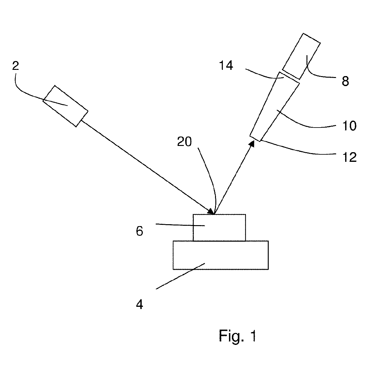
[0040]Referring to FIG. 1, X-ray apparatus includes an X-ray source 2, a sample stage 4 shown with a sample 6 and an energy dispersive X-ray detector 8. Such an arrangement is used in particular for X-ray fluorescence.

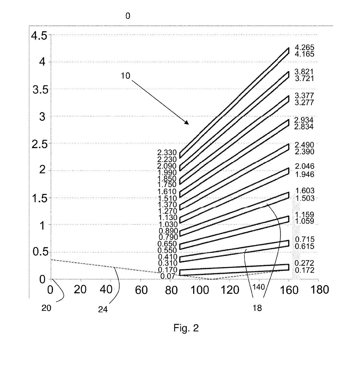
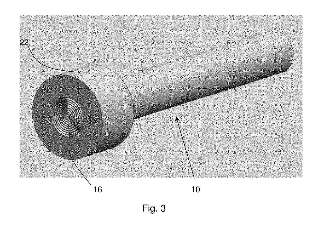
[0041]A collimator 10 is mounted in front of the energy dispersive X-ray detector 8 extending a central end 12 close to the sample stage to an outer end 14 adjacent to the detector as illustrated in more detail in FIG. 2. FIG. 3 shows a perspective view of the collimator 10.

[0042]The collimator 10 is made of a plurality of truncated cones 18 each formed of a metal, in the example the refractive metal tungsten. Note that FIG. 2 shows a section through the collimator and the space between the collimator and the focal spot 20 as well as the vanes 18 in a graphical format in which the vertical axis is highly exaggerated compared with the horizontal axis—the scales on both axes are in mm.

[0043]The sheets are a nominal 0.10 mm thick. Each sheet is formed into a truncated con...


PUM


Abstract

X ray apparatus includes a sample stage (4) for supporting a sample (6), an X-ray source (2) and an energy dispersive X-ray detector (8). A conical X-ray collimator (10) is provided either between the sample and the X-ray source or between the sample and the energy-dispersive X-ray detector, the conical X-ray collimator including a plurality of truncated cones arranged concentrically around a central axis, the truncated cones having a common apex defining a central measurement spot on the sample.

Description

CROSS-REFERENCE TO RELATED PATENT APPLICATIONS[0001]This application is a continuation of U.S. Non-Provisional patent application Ser. No. 15 / 366,632, filed Dec. 1, 2016, the entire contents of which is incorporated by reference herein as if expressly set forth in its respective entirety herein.FIELD OF INVENTION[0002]The present invention relates to X-ray fluorescence measurements and apparatus for measuring the same.BACKGROUND TO THE INVENTION[0003]A variety of different types of X-ray measurements are possible for analysing materials. In an X-ray fluorescence measurement, a beam of X-rays is directed at a sample and the resulting X-rays emitted by the sample are measured by an energy dispersive X-ray detector. Such a detector measures X-ray intensity as a function of energy or equivalently as a function of wavelength.[0004]For homogenous samples, including large crystalline structures, the sample area measured is often not critical. However, some samples such as powder mixtures a...

Claims


Application Information

Patent Timeline
Patent Type & Authority Applications(United States)
IPC IPC(8): G01N23/223B22F3/105G21K1/02
CPCG01N23/223B22F3/1055G21K1/02Y02P10/295B33Y80/00G01N2223/507G01N2223/316G01N2223/076G21K2207/00B33Y10/00G01N23/22B22F10/32B22F10/62B22F10/28B22F10/37G21K1/025Y02P10/25
Inventor HEGEMAN, PETRONELLA EMERENTIANABRONS, GUSTAAF CHRISTIAN
Owner PANALYTICAL BV
Why Eureka
Try Eureka