Interface between an outer end of a wing and a moveable wing tip device

a technology of wing tip and outer end, which is applied in the direction of wing adjustment, heat reduction structures, aircraft components, etc., can solve the problems of limited sliding contact movement along this length, or no sliding contact movement, and achieve the effect of facilitating the integration of the wing tip devi

Active Publication Date: 2019-05-30
AIRBUS OPERATIONS LTD
View PDF0 Cites 2 Cited by
  • Summary
  • Abstract
  • Description
  • Claims
  • Application Information

AI Technical Summary

Benefits of technology

The patent describes how to create a seal on a wing by cutting out a section of material that runs through the middle of the wing. This helps improve its performance during flight. The cut can be made in several ways depending on what design needs to be achieved. By doing this, researchers hope they can better control the airflow over the wing for more efficient flying.

Problems solved by technology

The technical problem addressed in this patent text relates to finding better ways to connect the fixed wing with the wing tip device during operation of the aircraft, while also allowing for separation of these components during ground operations without causing excessive wear or tear on the seal used to prevent leakage.

Method used


Image

  • Interface between an outer end of a wing and a moveable wing tip device
  • Interface between an outer end of a wing and a moveable wing tip device
  • Interface between an outer end of a wing and a moveable wing tip device

Examples


Embodiment Construction

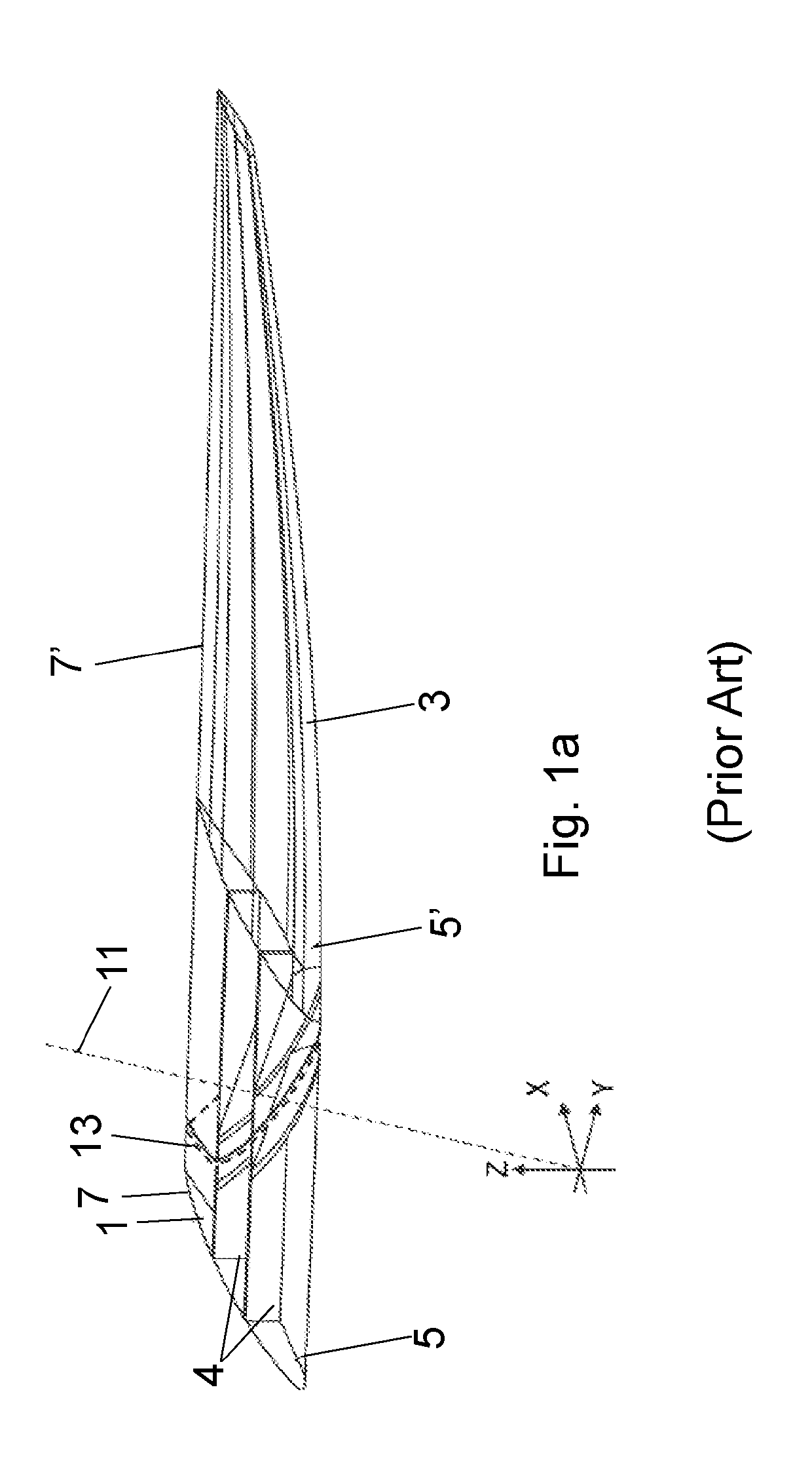
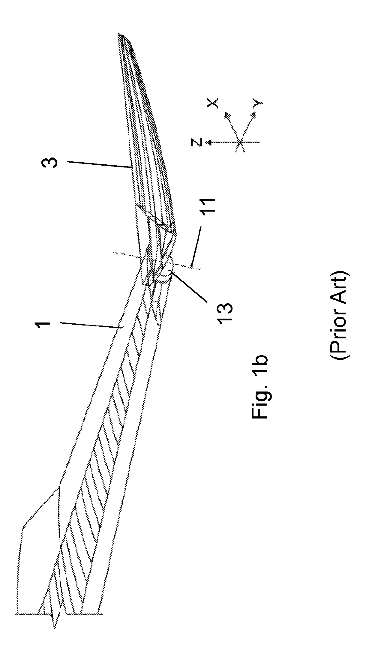
[0059]FIG. 1a is a perspective view of a fixed wing 1 and a wing tip device 3 on an aircraft shown in WO2015 / 150835. In summary, the wing tip device 3 is moveable between a flight configuration (FIG. 1a) and a ground configuration (FIG. 1b). In the flight configuration, the leading and trailing edges 5′, 7′ of the wing tip device 3 are continuations of the leading and trailing edges 5, 7 of the fixed wing 1. Furthermore, the upper and lower surfaces of the wing tip device 3 are continuations of the upper and lower surfaces of the fixed wing 1.

[0060]The wing tip device 3 is placed in the flight configuration for flight. In the flight configuration, the wing tip device 3 thus increases the span of the aircraft (thereby providing beneficial aerodynamic effects, for example, reducing the component of induced drag and increasing the lift). In principle, it would be desirable to maintain this large span at all times and simply have a large fixed wing. However, the maximum aircraft span is...


PUM


Abstract

An aircraft (1002) including a wing (1001), having a fixed wing (1005) with a wing tip device (1003) moveably mounted at the outer end thereof. The wing tip device (1003) is moveable between: a flight configuration; and a ground configuration. The wing tip device (1003) and the fixed wing (1005) are separated along an oblique primary cut plane (1013). The wing tip device (1003) and the fixed wing (1005) meet along an interfacing cut line (1035). The interfacing cut line (1035) includes a first length (1037) offset from the primary cut plane (1013) in a first direction; a second length (1041) that extends within a plane (P) containing the axis of rotation (1011), or a plane parallel thereto; and a transition section (1039) over which the interfacing cut line (1035) transitions from the first length to the second length. The second length may extend around the upper surface, around the leading edge and onto the lower surface.

Description


Claims


Application Information

Patent Timeline
Owner AIRBUS OPERATIONS LTD
Why Eureka
Try Eureka