Pneumatic Tire

Active Publication Date: 2019-05-23
YOKOHAMA RUBBER CO LTD
View PDF0 Cites 2 Cited by
  • Summary
  • Abstract
  • Description
  • Claims
  • Application Information

AI Technical Summary

Benefits of technology

The present technology provides a pneumatic tire with a single-ply belt layer that achieves good steering stability and reduces tire weight. The carcass layer shares the function of the belt layer and includes a curved carcass structure. The carcass cords are inclined in the tire width direction in the tread region and extend along the tire radial direction in the side region. This arrangement ensures that the carcass layer can effectively function as the belt layer. It also improves durability and flexural rigidity of the tire. Additionally, a belt reinforcing layer is provided to improve high-speed durability. Overall, the technology achieves a tire with improved performance and reduced weight.

Problems solved by technology

However, from the perspective of wear resistance and durability, it is difficult to achieve further reduction in weight with the method of reducing the thickness of each portion of the tire.
However, when the belt layer is completely removed from the tread portion, there is a problem in that steering stability cannot sufficiently be secured.

Method used


Image

  • Pneumatic Tire
  • Pneumatic Tire
  • Pneumatic Tire

Examples


examples

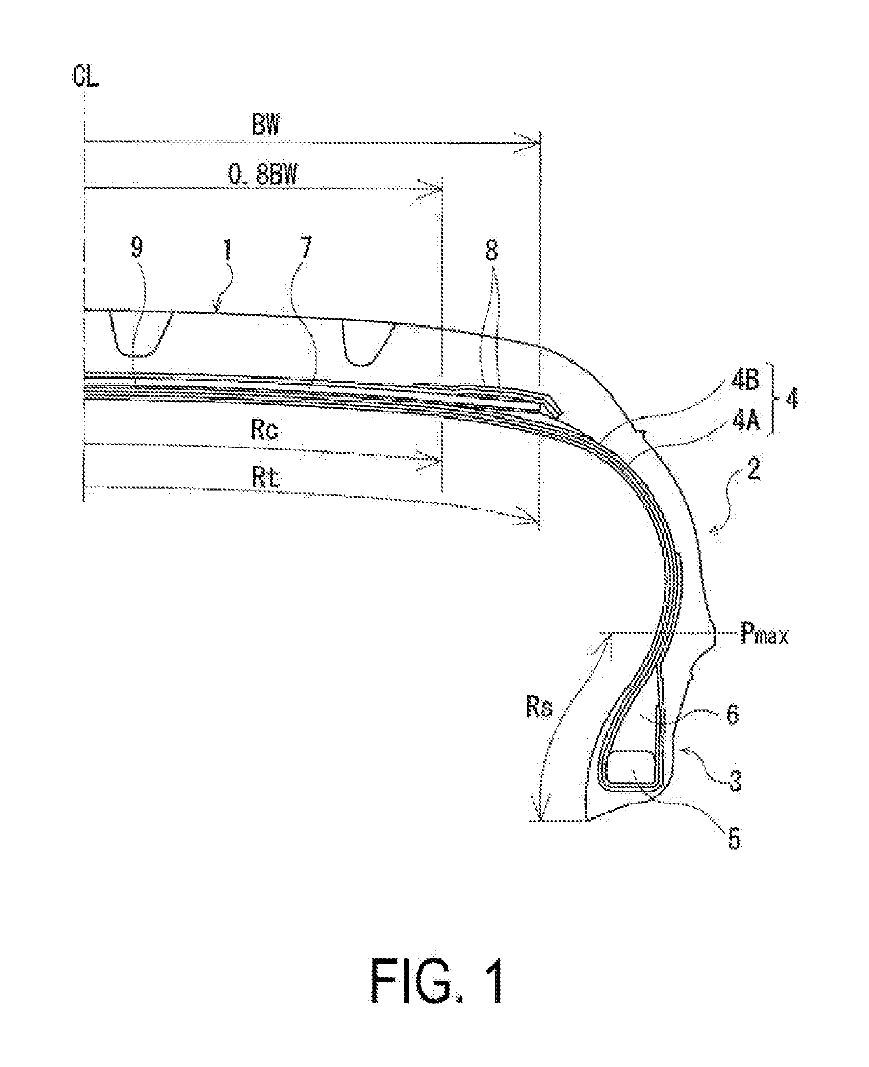
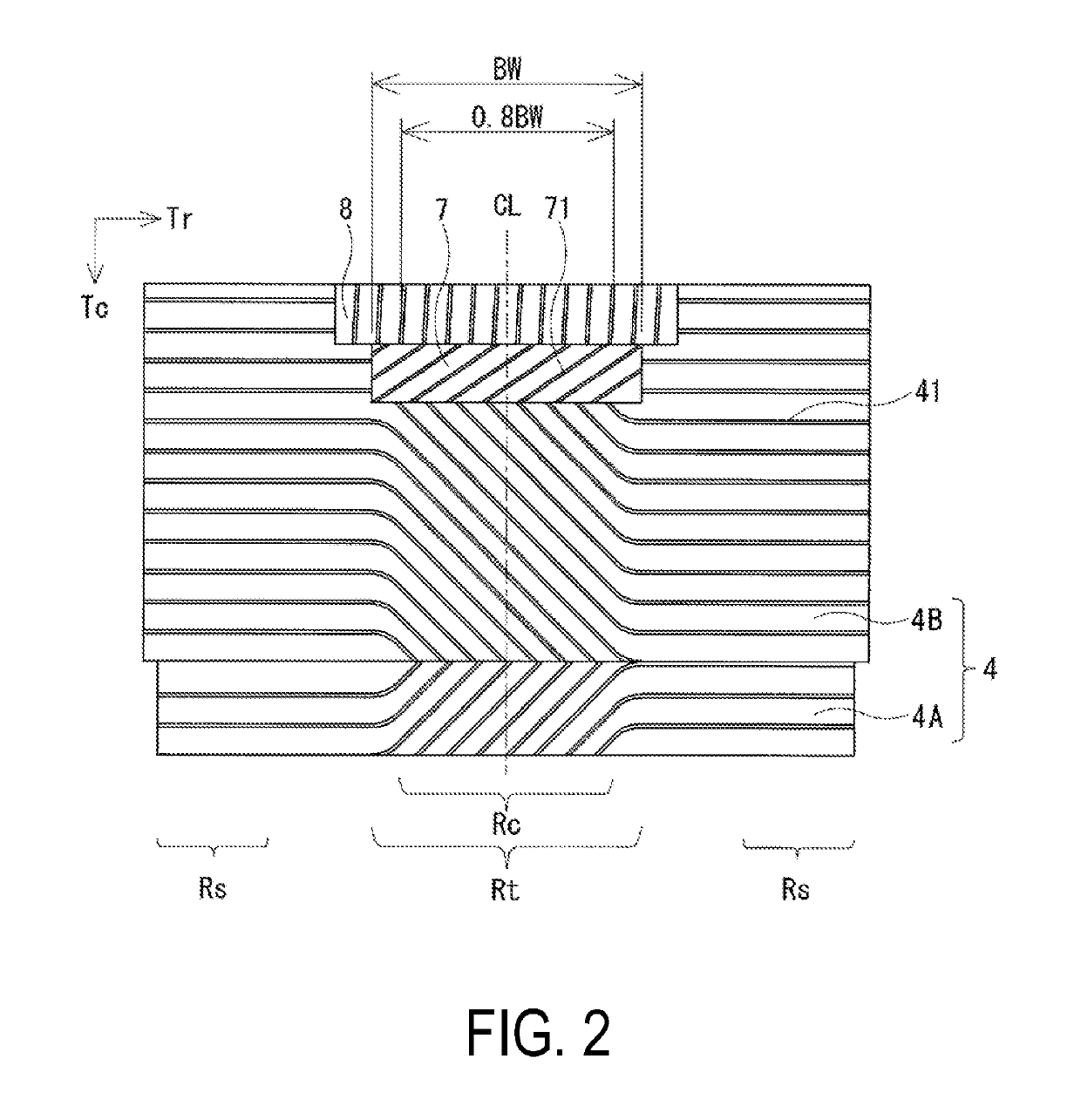
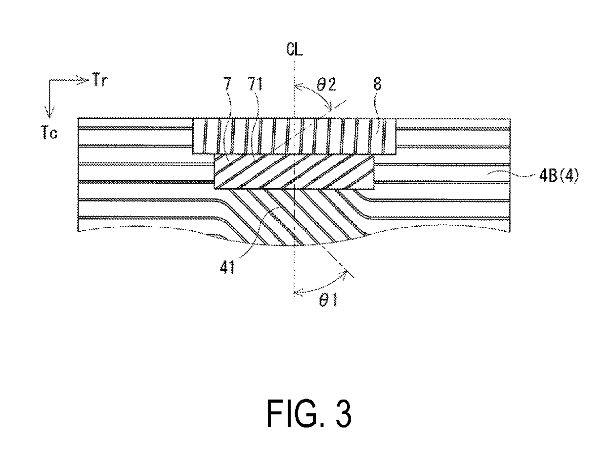
[0029]A tire for each of Examples 1 to 4 was manufactured in the following manner. The pneumatic tire had a tire size of 235 / 40R18, and included two carcass layers, and a single belt layer. The carcass layers included a plurality of carcass cords mounted between a pair of bead portions. The belt layer was positioned on an outer peripheral side of the carcass layers of a tread portion, and included a plurality of belt cords inclined with respect to a tire circumferential direction. Also, the carcass cords forming the carcass layers were inclined with respect to the tire radial direction in a tread region, and extended along the tire radial direction in a side region. The carcass cords forming the carcass layers and the belt cords forming the belt layer cross with each other in the tread region.

[0030]In each of Examples 1 to 4, as shown in Table 1, the cord angle in the inner carcass layer in the tread central region, the cord angle in the inner carcass layer in the side region, the c...


PUM


Abstract

Provided is a pneumatic tire including a belt layer. When the tread region indicates a region corresponding to a belt width of the belt layer and the side region indicates a region inward of a tire radial direction with respect to a tire maximum width position, the carcass cords forming the carcass layer are inclined with respect to the tire radial direction in the tread region, and at the same time, extend along the tire radial direction in the side region. The carcass cords forming the carcass layer and belt cords forming the belt layer cross with each other in the tread region.

Description

TECHNICAL FIELD[0001]The present technology relates to a pneumatic tire and more particularly relates to a pneumatic tire including a belt layer, in which a carcass layer shares a function of the belt layer to achieve a single-ply belt layer by employing a curved carcass structure in which an angle of a carcass cord continuously changes in a tread region and side regions so that the pneumatic tire can maintain good steering stability and achieve reduction in tire weight.BACKGROUND ART[0002]Generally, as a method of reducing weight of a tire, the thickness is reduced of rubber used for, for example, a cap tread and sides, which are portions of the tire large in area. However, from the perspective of wear resistance and durability, it is difficult to achieve further reduction in weight with the method of reducing the thickness of each portion of the tire.[0003]Meanwhile, for reduction in weight of the tire, there have been proposed various types of a tire which does not require an ind...

Claims


Application Information

Patent Timeline
IPC IPC(8): B60C9/06B60C9/20B60C9/07B60C9/09
CPCB60C9/06B60C9/20B60C9/07B60C9/09B60C2009/2016B60C2009/2019B60C2009/0425B60C9/02B60C9/08B60C9/18Y02T10/86
Inventor MATSUDA, JUNSATOH, YUJIKODAMA, YUJI
Owner YOKOHAMA RUBBER CO LTD
Why Eureka
Try Eureka