
Roulette table layout

a roulette table and layout technology, applied in the field of roulette table layout, can solve the problems of difficult to keep watch on all, weary of unscrupulous players, and surreptitious actions of croupiers, and achieve the effect of more excitement and more attentive observation

Inactive Publication Date: 2019-05-16
DANG TRI +1
View PDF45 Cites 0 Cited by
  • Summary
  • Abstract
  • Description
  • Claims
  • Application Information

AI Technical Summary

Benefits of technology

The present invention provides a roulette table that allows the dealer to operate it without assisting in placing players' bets. It also eliminates the need for surveillance cameras or observers to scan the entire table length. Games players can easily observe one another, and players will no longer need to lean on the glass casing surrounding the roulette wheel. This enables the dealer to muck chips and make change more efficiently. Overall, this invention enhances the overall experience of roulette games.

Problems solved by technology

Most particularly, casinos are weary of unscrupulous players, who in an effort to tip the odds to their favor, will surreptitiously do strange things to cheat.
At a busy table it is difficult for the croupiers to keep watch on all of the players during all of that time.
But security cameras have their limitations.
Although cameras allow security staff to see the layout of each table, they cannot always pan to the exact spot at the exact moment when the irregularity occurs.
Because the game of roulette is most often said to be that game whose odds most favor the house, and due to the heavy surveillance by the house and the oftentimes invasive security gadgetry, roulette is not as comfortable nor as popular as it might be otherwise.
In fact, at a crowded table, few if any players at the table can readily reach each number in the grid.

Method used


Image

  • Roulette table layout
  • Roulette table layout

Examples


Embodiment Construction

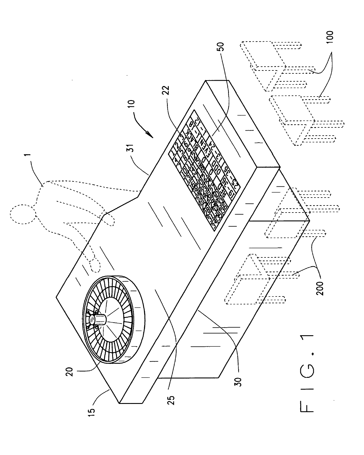
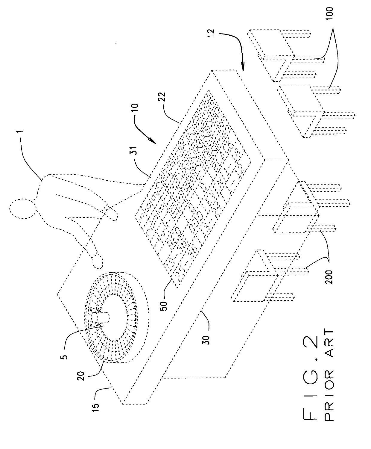
[0025]The invention may be best illustrated by FIG. 1 of the simple, but immensely useful and beneficial (to both the players and the house) casino roulette table layout 10 of my invention. This is in contrast to FIG. 2 with the prior art layout of table 10.

[0026]At FIG. 1, the dealer 1 is stationed proximate to the first short side 15 of the rectangular casino roulette table 10. A roulette wheel 20 is disposed atop the betting surface 25 of table 10, at proximately the first short side 15 of said table 10. Opposite of first short side 15 is second short side 12 of said rectangular roulette table 10. Connecting the two short sides 15 and 12, so as to define the rectangular shape are a long side 31 and a long side 30 opposite of 31. The betting surface 22 is layed out on table top 25 in the proximate center of table top 25, and is substantially defined by and consist essentially of a thirty-six numbered grid. There are also ancillary wagering spots 50 for betting on odd numbers, even...


PUM


Abstract

The thirty-six numbered, rectangular grid atop the betting surface of a standard casino roulette table, configured in 3 rows of twelve, if juxtaposed into an arrangement having rotated the grid 90 degrees, yields surprisingly advantageous results for both the casino and the players, by simplifying surveillance, enhancing player comfort, speeding up play, and enabling more convenient wagering.

Description

BACKGROUND OF THE INVENTIONField of the Invention[0001]The invention relates to gaming table designs; and particularly to an improved roulette table layout.Background of the Prior Art[0002]Roulette is a popular game of chance played against a croupier, also known as dealer, using a roulette wheel rotatably held within a structure called a bowl. The roulette wheel carries a plurality of numbered, red and black compartments that are formed on an upward facing surface that borders the periphery of the wheel. The roulette wheel, and bowl in which the wheel is mounted, sits on a table, the upper surface of which is laid out typically to delineate a grid of spaces that are colored either red or black and numbered to correspond with the compartments of the wheel.[0003]Wagers are made, by the players, by placing the stakes upon the marked spaces of the roulette table's grid. Each game is initiated when, after the wagers are placed, the croupier or dealer spins the roulette wheel and sets a ...

Claims


Application Information

Patent Timeline
Patent Type & Authority Applications(United States)
IPC IPC(8): A63F5/00
CPCA63F5/00A63F2003/00164
Inventor DANG, TRIPHUNG, WILLIAM
Owner DANG TRI
Learn More