
Motor control device, control system, and motor control method

a technology of motor control and control system, which is applied in the direction of computer control, program control, instruments, etc., can solve the problems of increasing and increasing the number of data required, so as to prevent the decrease in the stability of the motor control and reduce the load on the motor control devi

Active Publication Date: 2019-05-09
FANUC LTD
View PDF0 Cites 0 Cited by
  • Summary
  • Abstract
  • Description
  • Claims
  • Application Information

AI Technical Summary

Benefits of technology

The present invention is a motor control device, system, and method that prevents instability in the motor control. It reduces the workload on the motor control device and ensures stability in motor control even if the control periods of multiple numerical controllers and the motor control device differ.

Problems solved by technology

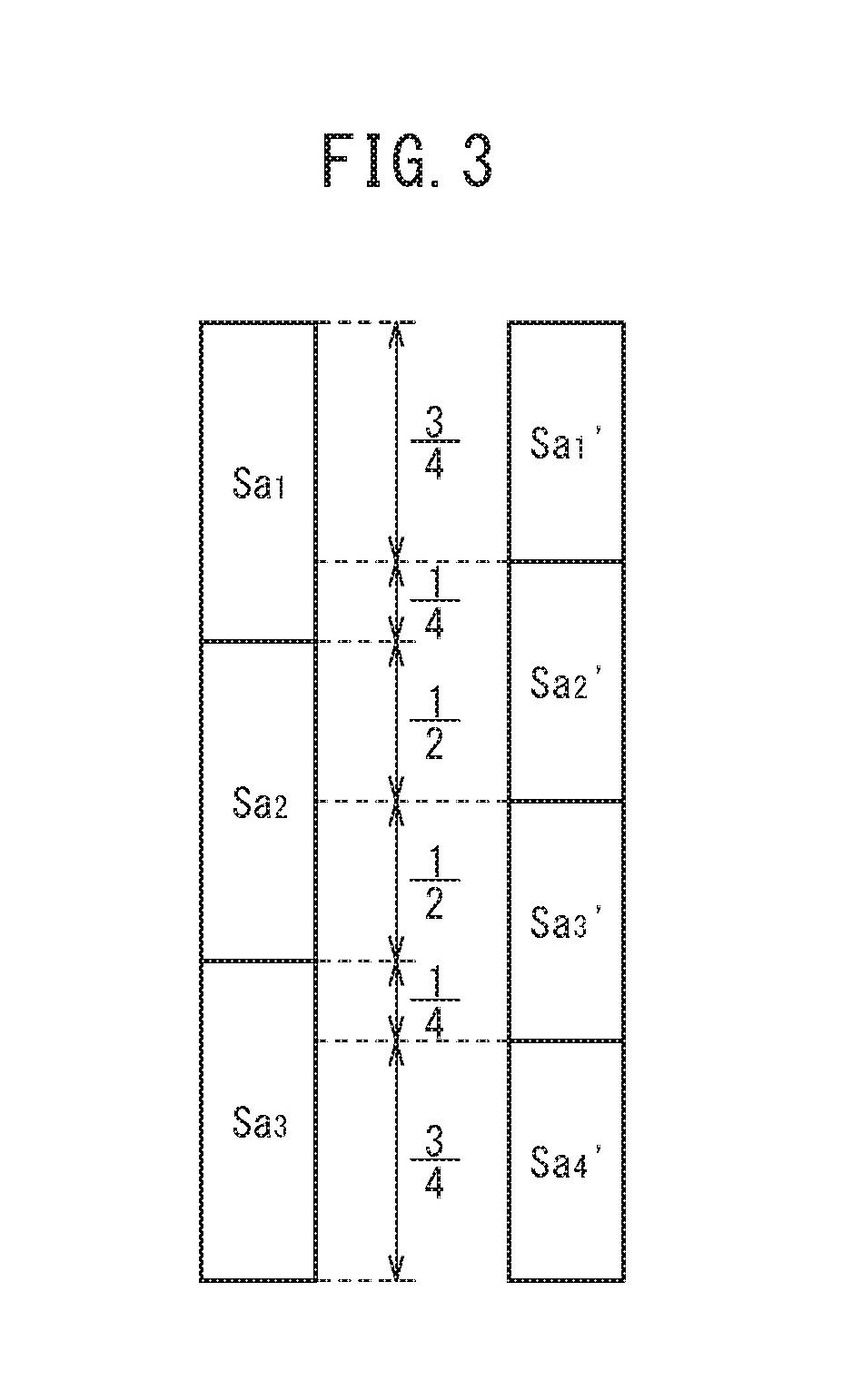
However, when a control period of the numerical controller differs from the control period of the motor control device, a problem occurs in that an excess or a deficiency occurs in the number of data required for the control, and the control of the motor is delayed.
As a result, fluctuations in speed and positional deviations occur, and the stability of the motor control deteriorates.

Method used


Image

  • Motor control device, control system, and motor control method
  • Motor control device, control system, and motor control method
  • Motor control device, control system, and motor control method

Examples


embodiments

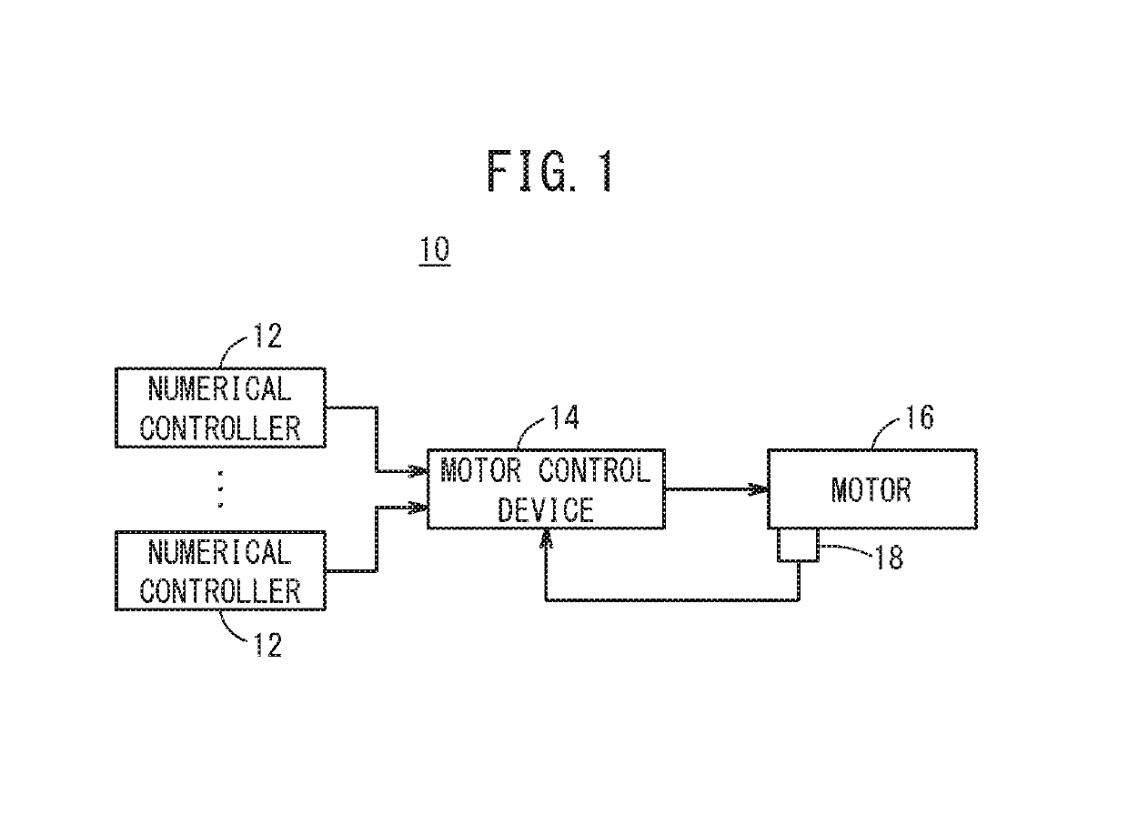
[0017]FIG. 1 is a diagram showing a schematic configuration of a control system 10 according to the present embodiment. The control system 10 comprises a plurality of numerical controllers 12, a motor control device 14, and a motor 16.

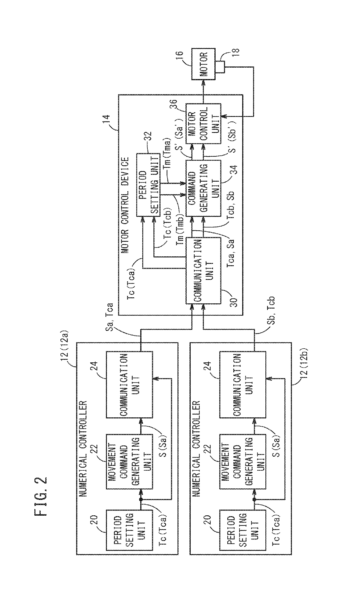
[0018]Control periods (first control periods) Tc of the plurality of numerical controllers 12, and control periods (second control periods) Tm of the motor control device 14 differ from each other. Further, it is assumed that the control periods Tc of the plurality of numerical controllers 12 differ from each other.

[0019]The numerical controllers 12 are higher order control devices for controlling the motor 16 in accordance with a program or an operator's operations for driving the motor 16. The numerical controllers 12 output (transmit) to the motor control device 14 commands (hereinafter referred to as movement commands) S for driving the motor 16. Stated otherwise, driving of the motor 16 is controlled by the plurality of numerical controllers 12.

[0...


PUM


Abstract

A motor control device is equipped with a command receiving unit adapted to receive movement commands and first control periods of the movement commands from each of a plurality of numerical controllers, a command generating unit which, on the basis of the plurality of first control periods and a plurality of second control periods in accordance with each of the plurality of first control periods, is adapted to generate movement commands of the plurality of second control periods from the movement commands of the plurality of first control periods, and a motor control unit adapted to control a motor in accordance with the plurality of movement commands generated by the command generating unit.

Description

CROSS-REFERENCE TO RELATED APPLICATION[0001]This application is based upon and claims the benefit of priority from Japanese Patent Application No. 2017-214608 filed on Nov. 7, 2017, the contents of which are incorporated herein by reference.BACKGROUND OF THE INVENTIONField of the Invention[0002]The present invention relates to a motor control device, a control system, and a motor control method, which serve to control a motor.Description of the Related Art[0003]As described in Japanese Laid-Open Patent Publication No. 2016-200523, a motor control device controls a motor on the basis of commands from a numerical controller.SUMMARY OF THE INVENTION[0004]However, when a control period of the numerical controller differs from the control period of the motor control device, a problem occurs in that an excess or a deficiency occurs in the number of data required for the control, and the control of the motor is delayed. As a result, fluctuations in speed and positional deviations occur, an...

Claims


Application Information

Patent Timeline
Patent Type & Authority Applications(United States)
IPC IPC(8): G05B19/406
CPCG05B19/406G05B2219/42267
Inventor TSUTSUMI, TOMOHISAMORITA, YUUKI
Owner FANUC LTD
Learn More