OSB Board and Use of the Same

a technology of osb board and osb insert, which is applied in the field of osb board, can solve the problems of inconvenient use, undercutting of the panel, and inconvenient use of the panel with such a profile inser

Active Publication Date: 2019-04-18
KRONOTEC
View PDF24 Cites 0 Cited by
  • Summary
  • Abstract
  • Description
  • Claims
  • Application Information

AI Technical Summary

Benefits of technology

[0024]When laying the OSB boards, the rebate according to the invention allows the OSB boards to be easily laid down. For this reason, the OSB boards according to the invention are also good for the panelling of a stud frame structure for producing a wall, by contrast with tongue-and-groove connections, which can only be pushed or inserted into one another.
[0057]The coating or laminating of surfaces of OSBs with cardboard paper has many advantages. Applying it to the surface of the board on one side provides a smooth coatable surface with properties similar to a plasterboard or fibre plasterboard, which has the additional properties of a wooden board such as very good fastening possibilities (for example by means of screws or staples) or special dowels. Such a modified OSB board can be used as a finished surface. The modified OSB boards can also be used for static and air-tight requirements.

Problems solved by technology

However, laying OSB boards vertically, for example as wall panels, with a tongue-and-groove connection involves the user expending some force, and is consequently impractical.
The approach proposed here uses panel edge bevelling, which bring about an undercut of the panels.
However, panels with such a profiled insert are not suitable for panelling a stud frame structure for producing a wall, because it is also necessary here for the person laying the panels to exert a relatively great force.
However, plasterboards are normally very heavy (density of over 1200 kg / m3) and require knowledge and some effort to be fitted.

Method used


Image

  • OSB Board and Use of the Same
  • OSB Board and Use of the Same
  • OSB Board and Use of the Same

Examples


Embodiment Construction

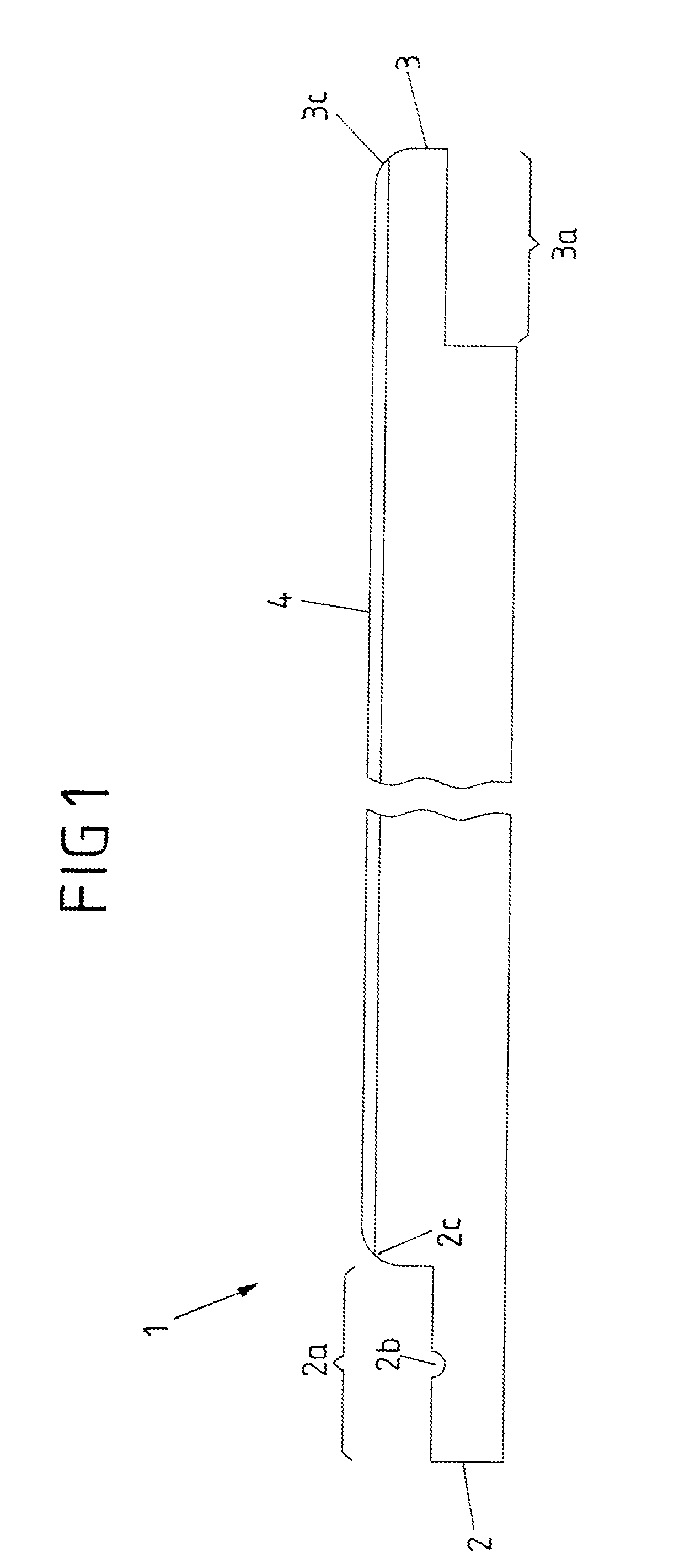
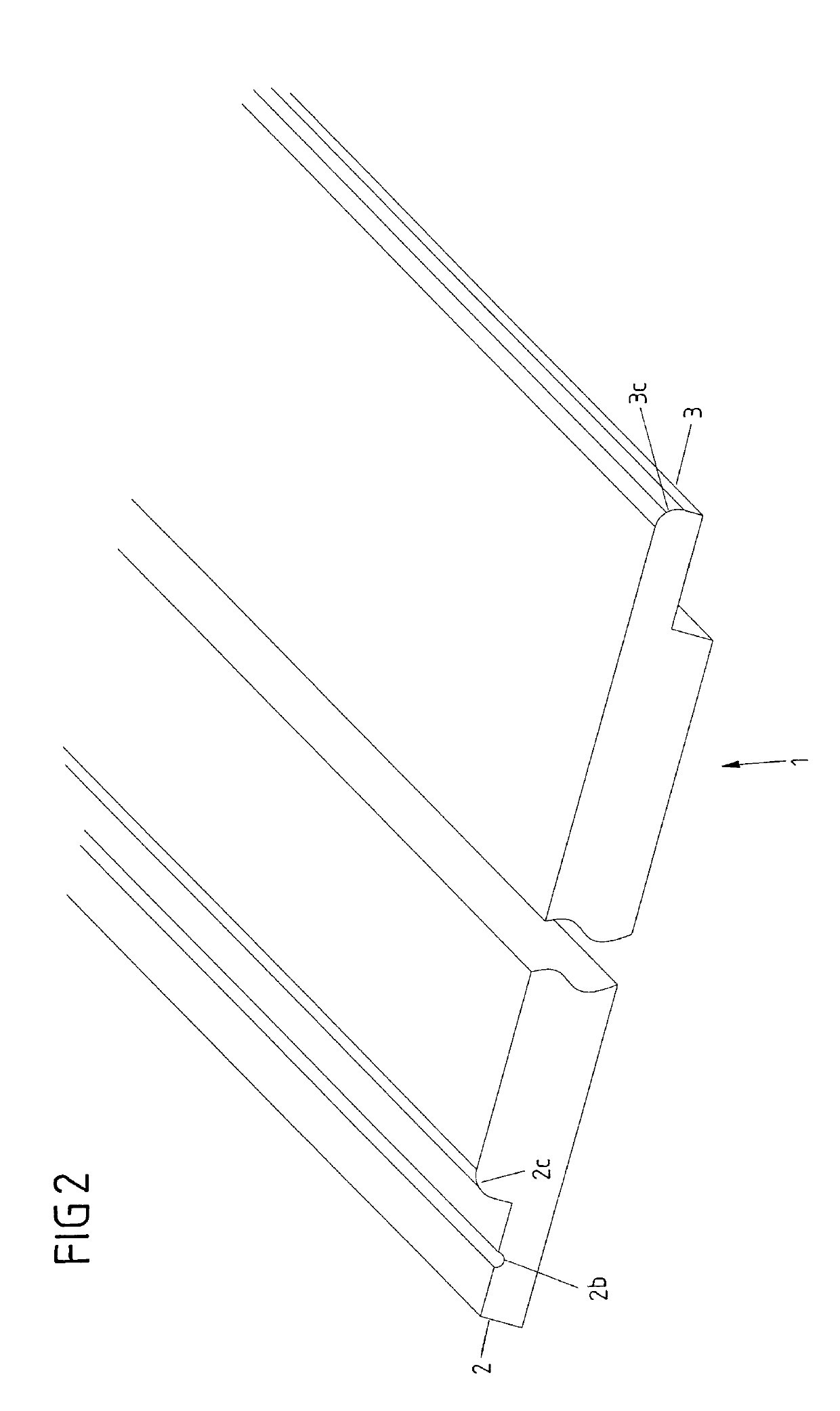
[0069]FIG. 1 shows a schematic cross-sectional view of an OSB board 1 with a width of between 625 and 2800 mm, which is provided on each of the opposite board edges 2, 3 with a simple rebate 2a, 3a, the two rebates 2a, 3a being formed so as to complement one another.

[0070]Correspondingly, the rebate 2a in the board edge 2 protrudes in a lower region of the board edge 2 and is set back in an upper region, whereas in the case of the complementing rebate 3a the upper region of the board edge 3 protrudes and the lower region is set back.

[0071]The width of the two rebates 2a, 3a is in each case 30 mm. The depth of the rebate corresponds respectively to half the thickness of the OSB board; i.e., in the case of a board thickness of between 9 and 40 mm, the depth of the rebate is 4.5 to 20 mm.

[0072]Provided in the surface of the rebate 2a is a rounded groove 2b as an insert channel for a glue tube or glue strip. The rounded groove 2b has a radius of 3 mm.

[0073]Laminated on the upper side of...


PUM

PropertyMeasurementUnit
radiusaaaaaaaaaa
radiusaaaaaaaaaa
widthaaaaaaaaaa

Abstract

The present invention relates to an OSB board with at least two board edges lying opposite one another, in particular two opposite longitudinal edges, where the upper side of the OSB board is provided with at least one layer of a cardboard paper. The board edges respectively on the upper side of the board have a rounding with a radius of between 3 and 10 mm. Each of the two opposite board edges has an offset in form of a simple rebate, the rebate in the one board edge complementing the rebate in the opposite board edge. At least one glue tube in each case is provided in at least one of the opposite offsets of the rebates, in particular in at least one groove.

Description

CROSS-REFERENCE TO RELATED APPLICATION[0001]This application claims priority to European Patent Application No. 17 196 384.6 filed Oct. 13, 2017, the disclosure of which is hereby incorporated in its entirety by reference.BACKGROUND OF THE INVENTIONField of the Invention[0002]The present invention relates to a modified OSB board with a novel connection profile and to the use thereof for wall and / or ceiling panelling.Description of Related Art[0003]Oriented strand boards, also known as OSB boards, are engineered wood boards produced from long slender strands. OSB boards are increasingly being used in the construction of timber-built and prefabricated houses, because OSB boards are lightweight and nevertheless meet the static requirements with which building boards legally have to comply. Thus, OSB boards are used as building boards and as wall or roof panelling or else in the floor area.[0004]The OSB boards that are used in a wide variety of areas of interior finishing must be fixed ...

Claims


Application Information

Patent Timeline
Patent Type & Authority Applications(United States)
IPC IPC(8): E04F13/08B32B3/06B32B21/06B32B21/02E04C2/12E04F13/10
CPCE04F13/0896B32B3/06B32B21/06B32B21/02E04C2/12E04F13/0866E04F13/10B32B2607/00B32B2471/00B32B2419/06E04F2201/0107E04F2201/026E04F2201/07E04F13/0864E04F13/0894E04F2201/0138E04C2/24B32B1/04
Inventor SAUTER, HARALD
Owner KRONOTEC
Why Eureka
Try Eureka