
Improvements in printing plate cell patterning

Active Publication Date: 2019-04-18
SANDON GLOBAL ENGRAVING TECH +1
View PDF0 Cites 1 Cited by
  • Summary
  • Abstract
  • Description
  • Claims
  • Application Information

AI Technical Summary

Benefits of technology

The patent describes a method for processing images to create a repeating pattern of pixels. The first step involves processing the image to create a first pattern of pixels, where each pixel has a unique off-center position. The second step involves creating a second pattern of pixels that is a simple version of a checkerboard pattern. The second pattern has different diagonal angles between adjacent pixels in consecutive rows, which allows for a more elongated shape of the pixels. This results in a pattern where the pixels have different sizes and shapes, which is believed to improve the quality of printing.

Problems solved by technology

The source artwork image, being digital and possibly being represented in vector form, typically utilizes an extremely extensive color palette (>16×106 colors is common), and is, at least in its original format, completely unsuitable for any large-scale printing technique such as flexography, and therefore significant amounts of pre-processing of the artwork image are required.
Despite the advances in both screening techniques and plate cell patterning, there is nevertheless still room for improvement, particularly as regards the printing of solid colors, or of shadows having high tonal values, because the screening techniques described do not translate particularly well to the areas of the printing plate where relatively high densities of dots (or, in the digital domain in a digital screen separation image, “on” pixels constituting them) are required in order to print them.

Method used


Image

  • Improvements in printing plate cell patterning
  • Improvements in printing plate cell patterning
  • Improvements in printing plate cell patterning

Examples


Embodiment Construction

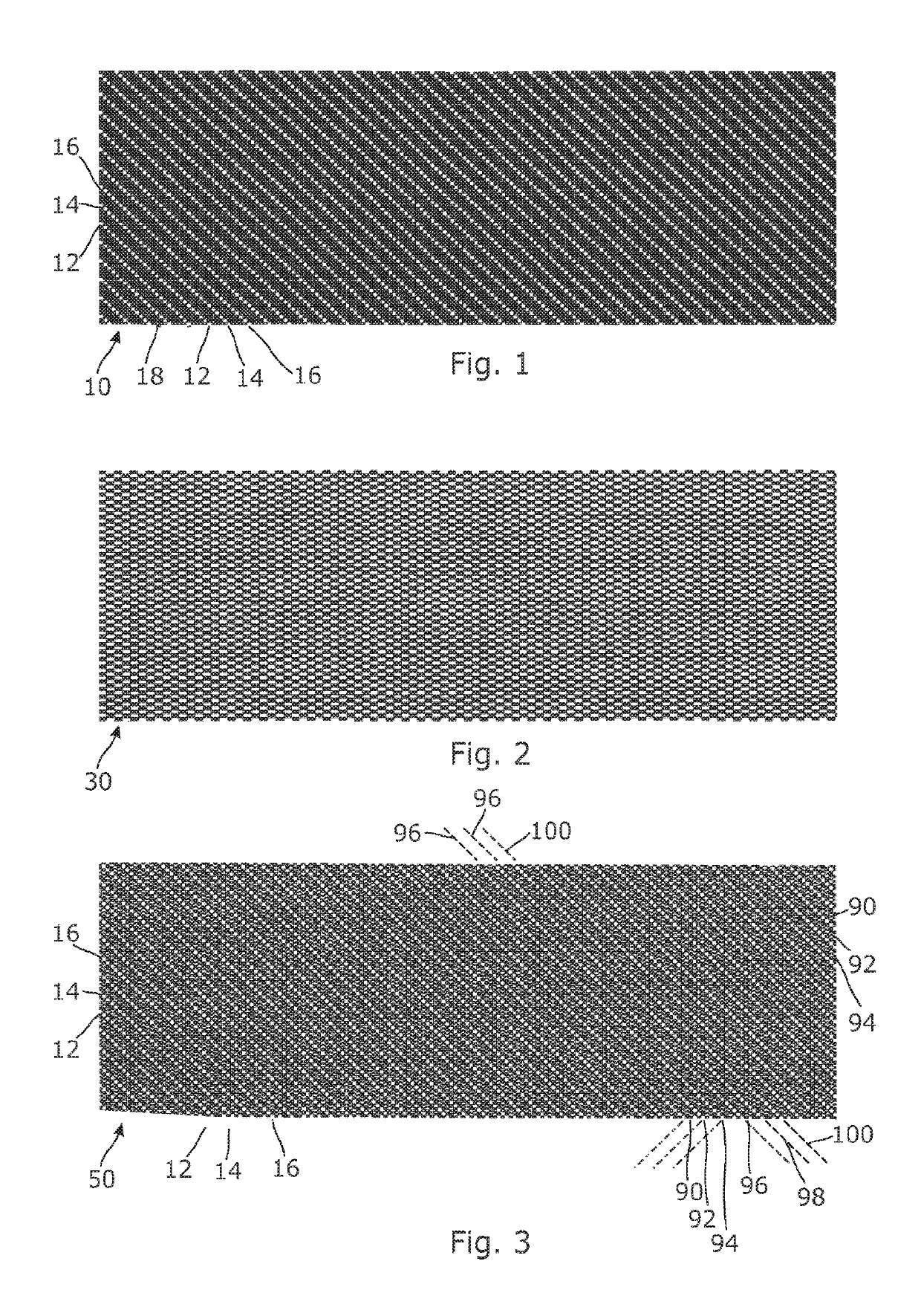
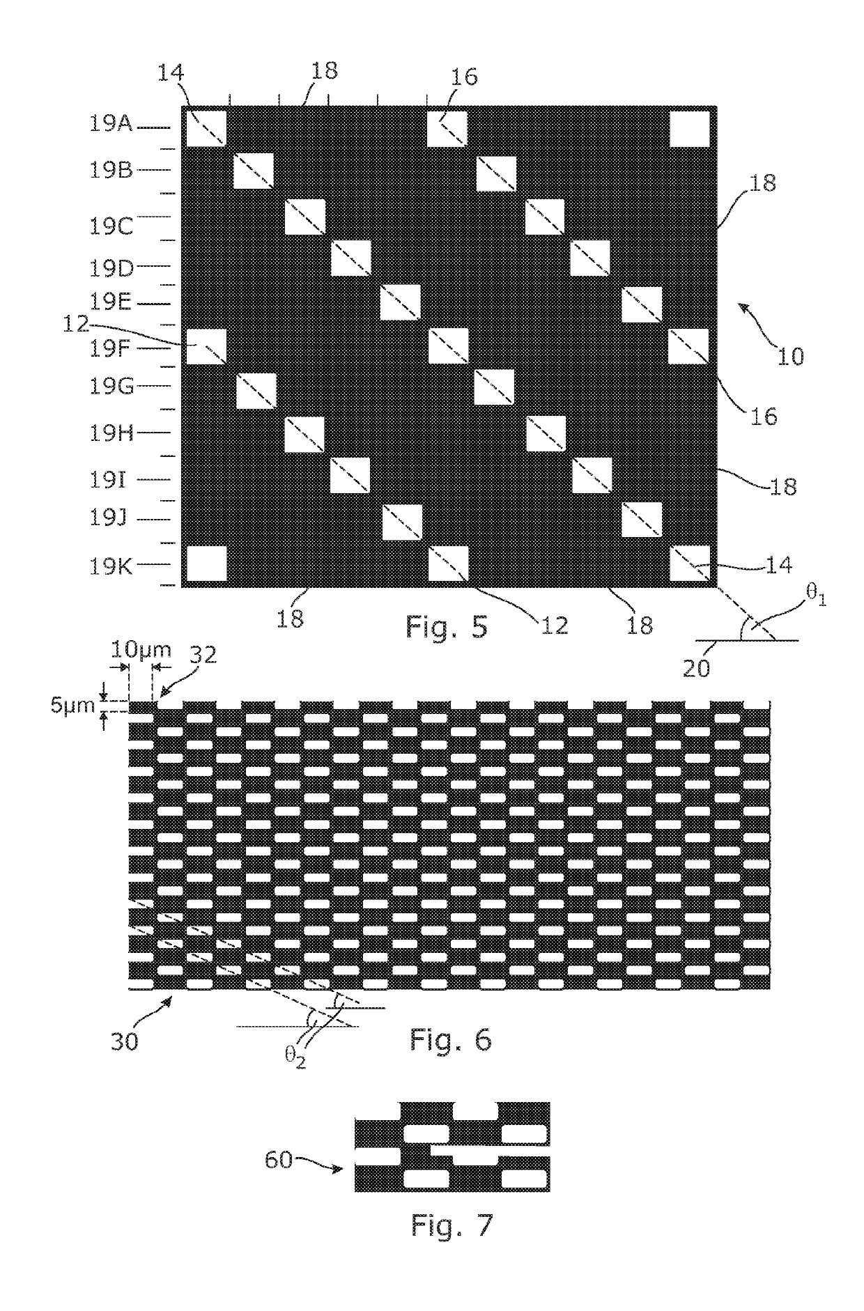
[0039]Referring firstly to FIGS. 1 and 5, there is shown a surface pattern pixel matrix 10 in which diagonally orientated rows of individual white “off” pixels 12, 14, 16 are provided in an otherwise solid area of black “on” pixels, as can be seen more clearly and enlarged in FIG. 5.

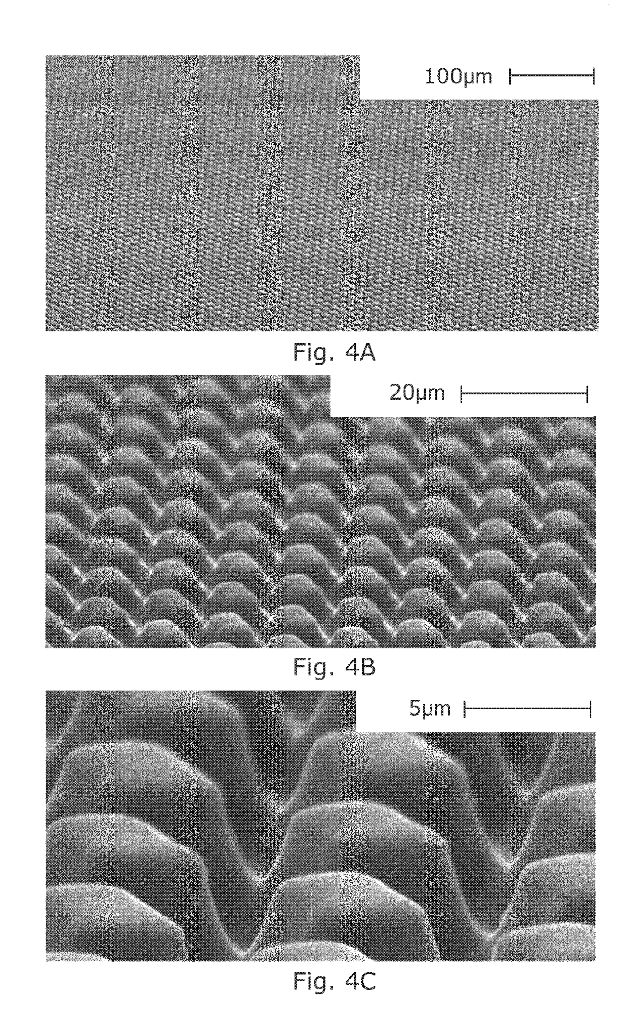
[0040]As will already be apparent from the foregoing, the patterns shown in the various figures can exist both virtually in the digital domain, e.g. within the 1-bit TIF files created as a result of the various RIPs applied to a single (CMYK or other) color separation of an original artwork image (not shown), and in the physical domain, e.g. as surface patterns appearing on the uppermost surface of relief areas of printing plates manufactured using any of the various CtP or computer-to-film technologies currently well known and widely practiced. The white “off” pixels of the former translate directly and exactly to depressions and / or channels in the latter, whereas the black “on” pixels of the former tra...


PUM


Abstract

A printing plate includes a plurality of relief areas which stand proud of a floor of the plate, each of the relief areas having an uppermost surface to which, in use, is applied a liquid which is borne by the uppermost surface and subsequently contactingly transferred to a substrate material. A predetermined pattern of depressions define a corresponding pattern of islands within the uppermost surface. The depressions within the uppermost surface include at least primary depressions of a first size and substantially geometric first cross-sectional shape, and secondary depressions, being of smaller cross-sectional area than the primary depressions and having a second cross-sectional shape which is distinctly more elongate than the first cross-sectional shape.

Description

CROSS-REFERENCE TO RELATED APPLICATION[0001]This application claims priority to PCT Application No. PCT / EP2017 / 055563, filed on Mar. 9, 2017, which claims priority to GB1604532.0, filed Mar. 17, 2016, each of which is incorporated by reference in its entirety.FIELD OF THE INVENTION[0002]The present invention relates to improvements in printing plate cell patterning, particularly to cell patterns applied to and appearing in flexographic printing plates, such cell patterns commonly being applied over a proportion or the entirety of the surface of the ink-bearing relief portions of such plates.[0003]Although the following description is provided with almost exclusive reference to flexography and the plates (or sleeves) adapted for use therein, it should be understood that the present invention may have wider application. Indeed, the invention may find application to any plate provided with relief features which are adapted, in use, to receive and bear a liquid so that said liquid effec...

Claims


Application Information

Patent Timeline
IPC IPC(8): B41N1/12B41N1/22H04N1/52H04N1/405
CPCB41N1/12B41N1/22H04N1/52H04N1/4057
Inventor LOWES, TREVOR
Owner SANDON GLOBAL ENGRAVING TECH
Learn More