
Laser assisted ultrasound guidance

a technology of assisted ultrasound and guidance, applied in the direction of ultrasonic/sonic/infrasonic diagnostics, application, diagnostic recording/measuring, etc., can solve the problems of difficult to maintain the orientation of the needle, the needle may have passed through some unforgiving non-target anatomical structure, and the needle may not be able to be positioned correctly

Active Publication Date: 2019-04-11
HASTINGS GEOFFREY STEVEN
View PDF2 Cites 6 Cited by
  • Summary
  • Abstract
  • Description
  • Claims
  • Application Information

AI Technical Summary

Benefits of technology

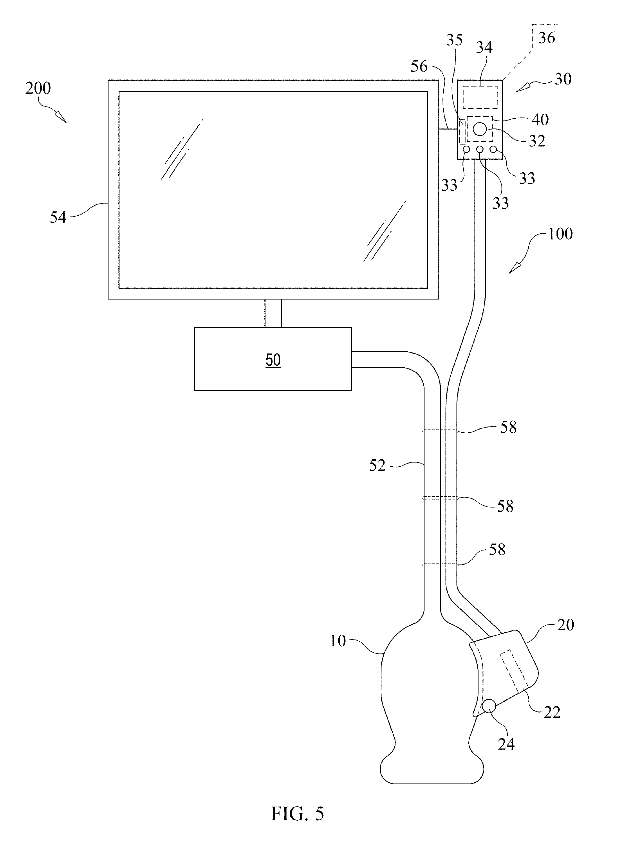
The invention is an apparatus that allows a medical instrument to be monitored while in use. It includes a camera and a display screen, which can show images taken by the camera. The camera is positioned so that the operator can view the instrument and guide line without having to look away from the ultrasound system display. The technical effect is that this allows for easier and more efficient monitoring of the instrument's use during a medical procedure.

Problems solved by technology

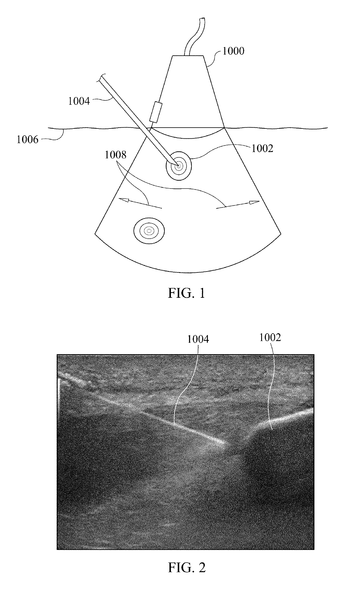
In the case where the needle 1004 and its path are not seen in the ultrasound image, or is seen as crossing the ultrasound image, there is a risk that the needle 1004 may have passed through some unforgiving non-target anatomical structure.
Lining up the needle 1004 can be done with the aid of a metallic or molded plastic guide, but most experienced operators do not use guides because they are expensive, clunky, easy to lose, and restrict the ability to reposition the needle 1004 pathway that the needle travels along.
It can be difficult to maintain the orientation of the needle upon switching back and forth between views.
This involves a half silvered mirror and mounting elements which add to the expense and complexity of the apparatus.

Method used


Image

  • Laser assisted ultrasound guidance
  • Laser assisted ultrasound guidance
  • Laser assisted ultrasound guidance

Examples


Embodiment Construction

[0051]Before the present invention is described, it is to be understood that this invention is not limited to particular embodiments described, as such may, of course, vary. It is also to be understood that the terminology used herein is for the purpose of describing particular embodiments only, and is not intended to be limiting, since the scope of the present invention will be limited only by the appended claims.

[0052]Where a range of values is provided, it is understood that each intervening value, to the tenth of the unit of the lower limit unless the context clearly dictates otherwise, between the upper and lower limits of that range is also specifically disclosed. Each smaller range between any stated value or intervening value in a stated range and any other stated or intervening value in that stated range is encompassed within the invention. The upper and lower limits of these smaller ranges may independently be included or excluded in the range, and each range where either,...


PUM


Abstract

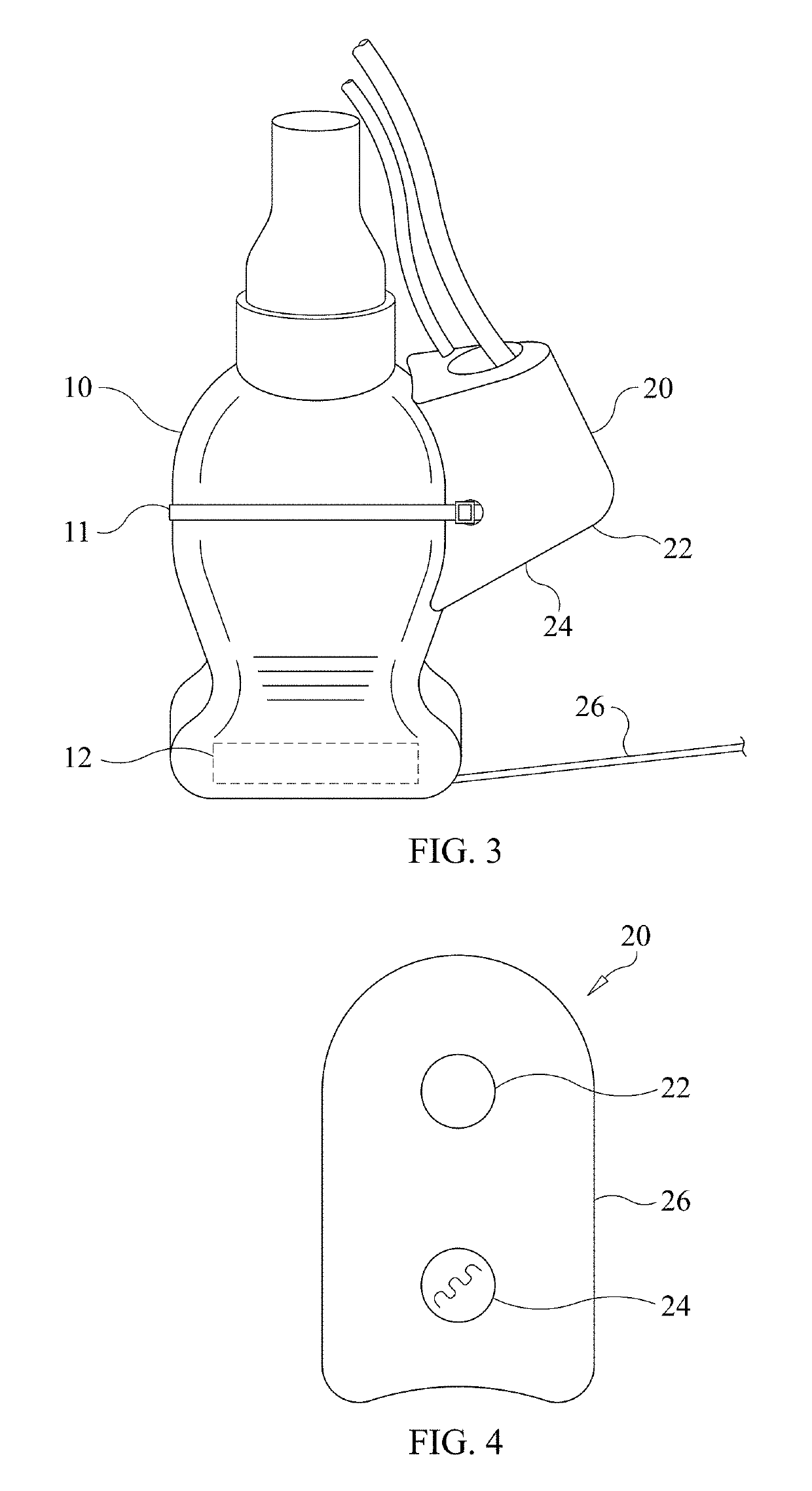
An instrument monitoring apparatus includes a guide and sensing component configured to be attached to an ultrasound probe. The guide and sensing component includes a source of illumination configured to project a light beam into a light plane; and a light receiver aligned with the light plane and configured to quantify an amount of light reflected from an object in the light plane to the light receiver by receiving the amount of reflected light and converting it to an electrical signal. A control component includes a processor configured to receive the electrical signal from the light receiver, and based on a magnitude of the amount of light represented by the electrical signal, determine whether the object is sufficiently within the light plane. The processor instructs output of a first signal when it is determined that the object is sufficiently within the light plane. The processor instructs output of a second signal that is distinct from the first signal, when it is determined that the object is not sufficiently within the light plane.

Description

BACKGROUND OF THE INVENTION[0001]Ultrasound is useful not only as a modality to detect and diagnose abnormalities, but also as a way to guide interventions such as biopsies, vascular access, tumor ablations, and drainage of fluid collections, body cavities, bile ducts, the urinary tract, and so on. FIG. 1 is an illustration of an ultrasound-guided biopsy as currently practiced. An ultrasound probe 1000 is placed against the skin of a patient in a location overlying a target 1002 within the body of the patient, so that ultrasound energy can be directed to the target for use in ultrasonic imaging of the target 1002 according to known principles.[0002]A needle 1004 is advanced through the skin 1006 of the patient and is advanced toward the target 1002 and into the target 1002 with visual guidance provided by viewing the ultrasound imaging provided by the ultrasound probe 1000. The needle 1004 can be visualized in the ultrasound image from the time that it enters the ultrasound beam 100...

Claims


Application Information

Patent Timeline
IPC IPC(8): A61B8/00A61B5/06A61B5/00
CPCA61B8/46A61B5/066A61B5/6851A61B8/0841A61B8/4444A61B8/4455A61B10/0283A61B2017/3413A61B90/13A61B2090/378A61B10/0233A61B5/0077A61B5/061A61B90/361
Inventor HASTINGS, GEOFFREY STEVEN
Owner HASTINGS GEOFFREY STEVEN
Learn More