Airflow for an Agricultural Harvesting Combine

a combine and airflow technology, applied in the direction of machines/engines, jet propulsion mounting, combustion air/fuel air treatment, etc., can solve the problems of removing a lot of residue and causing deleterious events, and achieve the effect of improving the sieve capacity

Active Publication Date: 2019-04-11
TRIBINE IND
View PDF0 Cites 0 Cited by
  • Summary
  • Abstract
  • Description
  • Claims
  • Application Information

AI Technical Summary

Benefits of technology

[0010]A large capacity fan pulls clean air from the top of the combine forward unit and pushes it out through the rear water radiator and out onto the hot exhaust treatment system to keep all surfaces free of chaff / dust; and pushes air out through side-mounted charge air coolers and onto the hot exhaust manifolds of both engines to also keep them chaff free; pushes air out through front hydraulic cooler and forward and down into the cleaning charge air fan (located in a round ring that is in the middle of the hydraulic reservoir) that is forcing air downwardly and through plenums associated with sidesheets and bulkheads that direct the high pressure air downwardly until it reaches the upper rear portion of the cleaning fan, where it comingles with air drawn from in front of the fan. Coincident with the rear plenum bulkhead are louvers that bleed off some of this air and direct it through the wall and rearward along the side of the rotor (concaves) to effectively pre-clean the MOG from the grain shooting through the concaves by the rotor.
[0012]The air from the cleaning fan, then, is propelled rearward and upward, being squeezed by the clean grain conveyor surface, through the main (center, full length) sieves to carry away chaff from the sieves to enhance sieve capacity.

Problems solved by technology

This design is want to do this because, if we allow the cleaning fan near the ground to pull all 30,000 from in front of the fan, it will likely pull a lot of residue off the ground (inlet vortices sweeping the soil) and plug the undersides of the sieves, which is a deleterious occurrence.

Method used


Image

  • Airflow for an Agricultural Harvesting Combine
  • Airflow for an Agricultural Harvesting Combine
  • Airflow for an Agricultural Harvesting Combine

Examples


Embodiment Construction

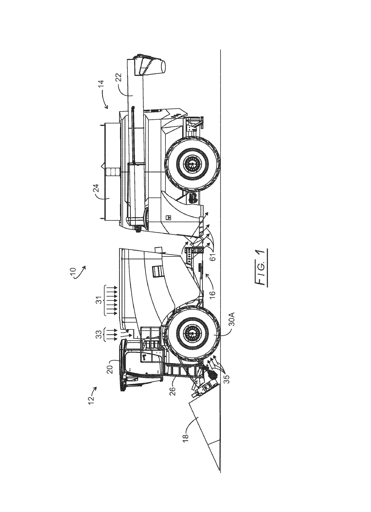
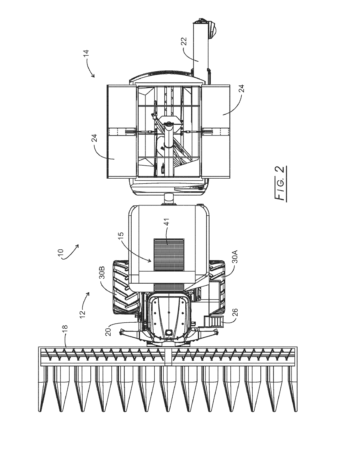
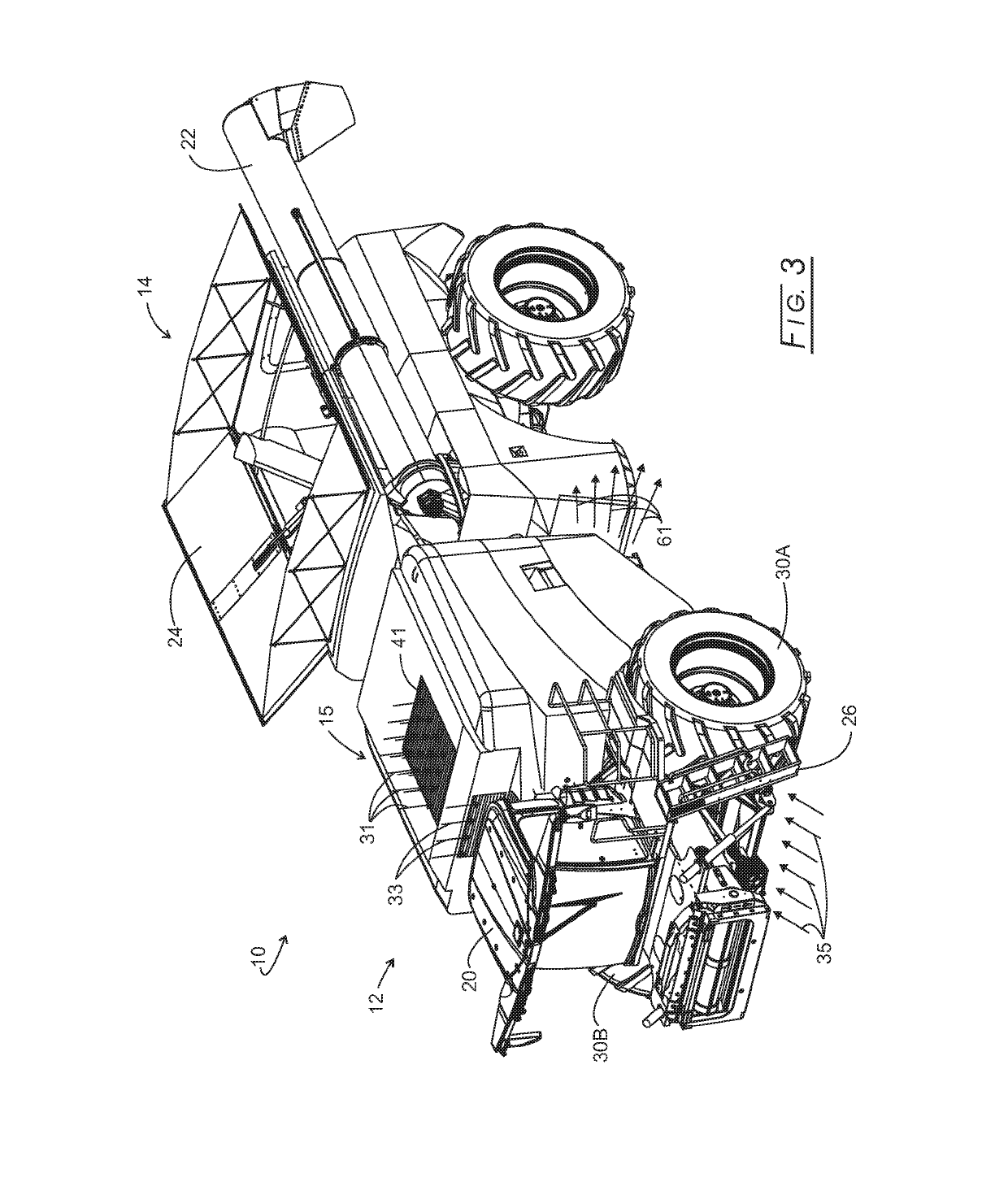
[0035]Referring initially to FIGS. 1, 2, 3, and 4, an articulated harvester, 10, consists of a powered PPU, 12, a rear grain cart, 14, and an articulation joint, 16, that connects PPU 12 with rear grain cart 14. The details of articulation joint 16 are disclosed in commonly owned application Ser. No. 14 / 946,827 filed Nov. 20, 2015. PPU 12 carries a grainhead, 18, operator's cab, 20, grain cleaning and handling assembly, and engines. PPU 12 is devoid of any grain storage, such being exclusive in rear grain cart 14. While both PPU 12 and rear grain cart 14 are shown being carried by wheel assemblies, one or both could be tracked. A screened air inlet, 15, is located atop PPU 12 where the air likely is the cleanest around harvesting combine 10.

[0036]An off-loading auger assembly, 22, is in the folded home position and being carried by rear grain cart 14. Grain cart 14 also bears a foldable roof, 24, shown in an open position, but which can fold inwardly to cover grain stored in rear gr...


PUM


Abstract

Disclosed is a complete engine cooling system for an engine carried by a grain harvesting combine having an internal combustion engine and hot exhaust components, and having a front operator cab. The system includes a generally horizontal fan assembly located atop the harvesting combine for drawing in air, a radiator associated with the engine and over which air flows for engine cooling, and charge air coolers for combustion air cooling, and air conditioning and hydraulic coolers, a centrifugal scroll that takes the drawn in air and removes entrained particles to produce a clean exhaust air and dirty exhaust air; and a filter assembly through which the pre-cleaned exhaust air flows for producing filtered air for admittance into the engine for combustion.

Description

CROSS-REFERENCE TO RELATED APPLICATIONS[0001]This application claims benefit of provisional application Ser. No. 62 / 358,629 filed Jul. 6, 2016, and is cross-referenced to commonly owned application Ser. No. ______, filed on even date herewith (attorney docket: DIL 2-040) and entitled “Dual Engine Agricultural Harvesting Combine”.STATEMENT REGARDING FEDERALLY SPONSORED RESEARCH[0002]Not applicable.BACKGROUND[0003]The present disclosure relates to harvesting articulated (jointed) combines and more particularly to improved airflow in the forward tractor or crop processing power unit (PPU) having dual engines with all grain stored in a rear grain cart.[0004]Most modern combines that utilize axially mounted threshing rotors have a single engine that is mounted transverse to the rotor (and direction of travel). Those combines typically use a bevel gear set to “turn” the engine's power to rotate the primary power consuming components—the rotor(s), header, and chopper(s). This configuration...

Claims


Application Information

Patent Timeline
Patent Type & Authority Applications(United States)
IPC IPC(8): A01D41/12F02M35/024F02B73/00A01F12/44B60K5/08F02M35/02F02M35/022A01D41/02F01P5/02B60K13/02B60K11/02B60K11/06B60K11/04B60K13/04
CPCA01D41/12F02M35/024F02B73/00A01F12/446A01F12/444B60K5/08F02M35/0216F02M35/0223A01D41/02F01P5/02B60K13/02B60K11/02B60K11/06B60K11/04A01D41/1252B60K13/04F02M31/20A01D41/06B60K15/03A01D41/1217
Inventor NELSON, DARREN J.MATOUSEK, ROBERT A.CLAERHOUT, BRYAN S.
Owner TRIBINE IND
Why Eureka
Try Eureka