A wheel loader front unit and a wheel loader

a front unit and wheel loader technology, applied in mechanical machines/dredgers, soil shifting machines/dredgers, constructions, etc., can solve the problems of increasing fuel consumption, increasing production costs, and relatively heavy wheel loaders, and achieves compact and robust design, simple and robust

Active Publication Date: 2019-03-07
VOLVO CONSTR EQUIP
View PDF4 Cites 1 Cited by
  • Summary
  • Abstract
  • Description
  • Claims
  • Application Information

AI Technical Summary

Benefits of technology

[0019]Thereby, an advantageous symmetric transfer of loads between the load arm and the hub supporting elements may be provided. The lateral positions of the slave hydraulic cylinders in relation to the lift arm provides for the slave hydraulic cylinders to advantageously extend substantially vertically as projected on a vertical lateral plane.
[0020]The frame may comprise two side plates and an intermediate central structure connecting the side plates to each other. Preferably, the side plates are arranged to be located, when the wheel loader front unit, ones a part of a wheel loader, laterally of the central structure in relation to a straight direction of travel of the wheel loader. The side plates may extend upwards and/or forwards beyond the central structure. The side plates may be substantially vertical when the wheel loader front unit forms a part of a wheel loader which is supported on a horizontal surface. The side plates may be arranged adjacent to the central structure. Eac

Problems solved by technology

An articulated frame steered wheel loader will normally be subjected to high loads during operation.
To withstand such loads, the amount of material in the structure of the wheel loader may be

Method used


Image

  • A wheel loader front unit and a wheel loader
  • A wheel loader front unit and a wheel loader
  • A wheel loader front unit and a wheel loader

Examples


Embodiment Construction

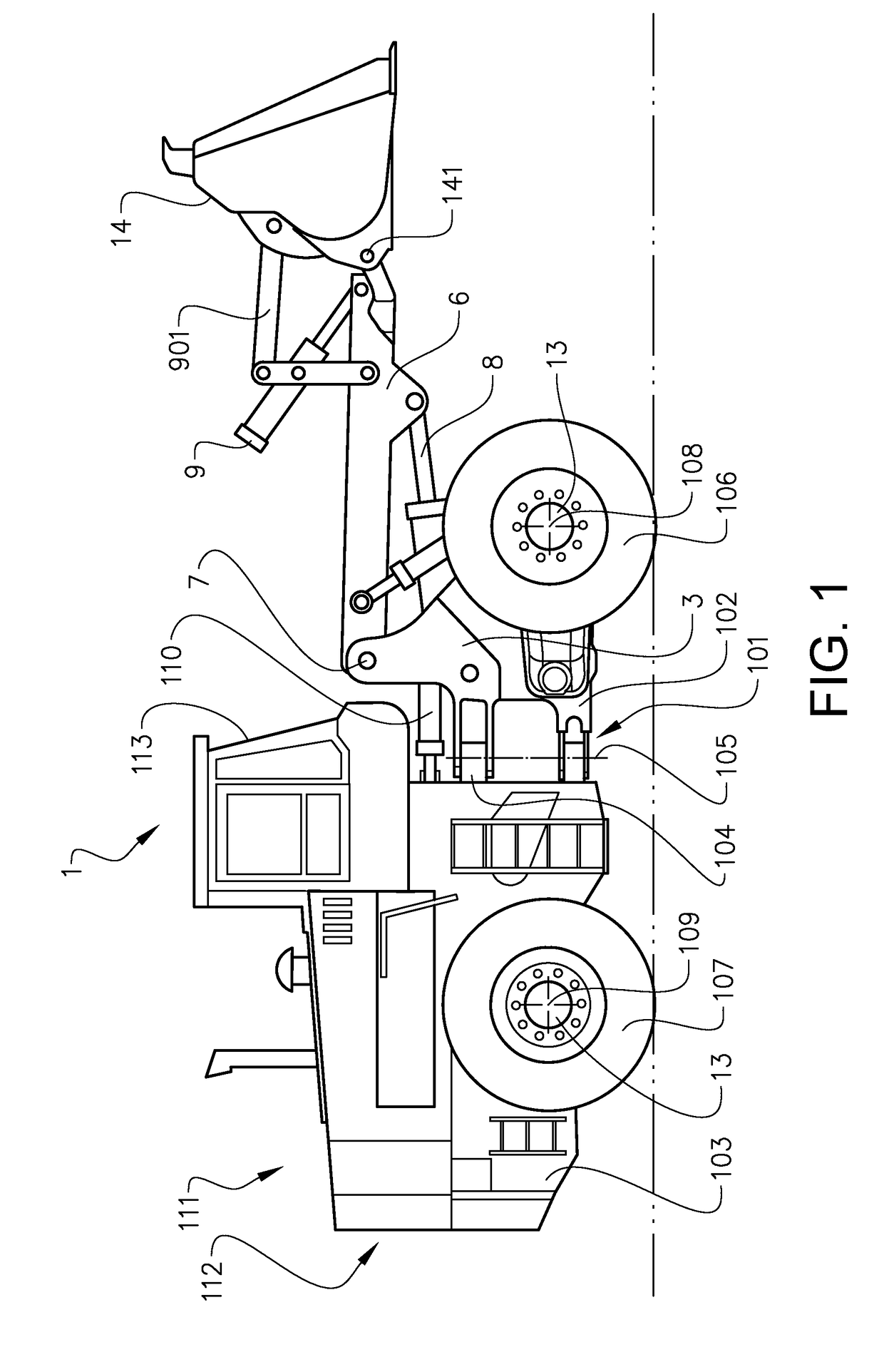
[0034]FIG. 1 is an illustration of a working machine 1 in the form of a wheel loader, The wheel loader comprises a body structure 101 with a front unit 102 and a rear unit 103. The front unit 102 comprises a flame 3 described closer below. The front unit 102 and the rear unit 103 are mounted to each other via a pivotable coupling 104. The front unit 102 and the rear unit 103 present two front wheels 106 and two rear wheels 107, respectively. The wheels are mounted to respective hub units 13 described closer below. The front wheels 106 define a front wheel axis 108 and the rear wheels 107 define a rear wheel axis 109.

[0035]The pivotable coupling 104 is arranged to allow the front and rear units to pivot in relation to each other around a pivot axis 105 which is substantially vertical when the wheel loader 1 is supported on a horizontal surface. Two steering hydraulic cylinders 110 are arranged on opposite sides of the wheel loader 1 for turning the wheel loader by means of relative m...


PUM


Abstract

The invention provides a wheel loader front unit including a frame, the wheel loader front unit further including two hub supporting elements, each hub supporting element being arranged on opposite sides outside of the frame for supporting a respective hub unit, a lift arm for supporting an implement of the wheel loader, the lift arm being arranged to be pivoted around a pivot connection to the frame by a main hydraulic cylinder, and a tilting hydraulic cylinder arranged to actuate a tilting movement of the implement in relation to the lift arm, wherein the wheel loader front unit further includes a slave hydraulic cylinder hydraulically connected to the tilting hydraulic cylinder for controlling the tilting movement of the implement when the lift arm is pivoted by the main hydraulic cylinder, wherein the slave hydraulic cylinder extends between the lift arm and one of the hub supporting elements.

Description

BACKGROUND AND SUMMARY[0001]The invention relates to a wheel loader front unit, and a wheel loader. The invention is applicable on working machines within the fields of industrial construction machines or construction equipment, in particular wheel loaders.[0002]A working machine, such as a wheel loader, is usually provided with a bucket, container, gripper or other type of implement for digging, carrying and / or transporting a load. For example, a wheel loader has a lift arm unit for raising and lowering the implement. Usually a hydraulic cylinder or a pair of hydraulic cylinders is arranged for raising the lift arm and a further hydraulic cylinder is arranged for tilting the implement relative to the lift arm.[0003]In addition, the working machine is often articulated frame-steered and has a pair of hydraulic cylinders for turning or steering the working machine by pivoting a front unit and a rear unit of the working machine relative to each other. The hydraulic system generally fu...

Claims


Application Information

Patent Timeline
IPC IPC(8): E02F9/08E02F3/28
CPCE02F9/0841E02F3/283E02F9/0808E02F3/433E02F9/08
Inventor OHLSSON, JOHANROSENPEK, NORBERT
Owner VOLVO CONSTR EQUIP
Why Eureka
Try Eureka