Eureka AIR delivers breakthrough ideas for toughest innovation challenges, trusted by R&D personnel around the world.

System and method for collecting maximum dimming parameter of a lamp group with a rated current unknown

a technology of dimming parameters and lamp groups, which is applied in the field of system and method for collecting maximum dimming parameters of lamp groups with a rated current unknown, can solve the problems of reducing the user's lighting experience, affecting and giving users a very good experience of using light, so as to increase the user's light experien

Inactive Publication Date: 2019-02-28
SELF ELECTRONICS CO LTD +2
View PDF3 Cites 0 Cited by
  • Summary
  • Abstract
  • Description
  • Claims
  • Application Information

AI Technical Summary

Benefits of technology

The present invention provides a system for collecting the maximum dimming parameter of a lamp group with a rated current unknown. This system can timely collect the maximum dimming parameter value, which ensures effective dimming at any time and prevents the dead zone phenomenon. This increases the user's light experience.

Problems solved by technology

However, these LED power supplies in some cases do not give users a very good experience of using light, for example, display lighting, In the museum, many users prefer to use a mobile phone or a camera to photograph the displayed items.
However, the existing LED power supply with variable output power makes the light source provided by the LED lamp often form a lot of photos taken by the mobile phone or the camera Streaks, so-called “blinks,” distort the photos, affecting the user's light experience.
If you also use the existing constant current dimming power supply, the maximum dimming current is often constant, which makes the output of the lamp has reached the brightest when the dimmer is adjusted to 70% or 50% or other range, that is, not full range, the remaining 30% or 50% or more of the dimming margin is redundant, invalid, it will reduce the user's lighting experience.
The leading cause of the above phenomenon is that it is difficult for the dimming power supply to determine the maximum current of the lamp group whose rated current is unknown.

Method used


Image

  • System and method for collecting maximum dimming parameter of a lamp group with a rated current unknown
  • System and method for collecting maximum dimming parameter of a lamp group with a rated current unknown

Examples


Embodiment Construction

[0019]The present application is illustrated by way of the following detailed description based on of the accompanying drawings. It should be noted that illustration to the embodiment in this application is not intended to limit the invention.

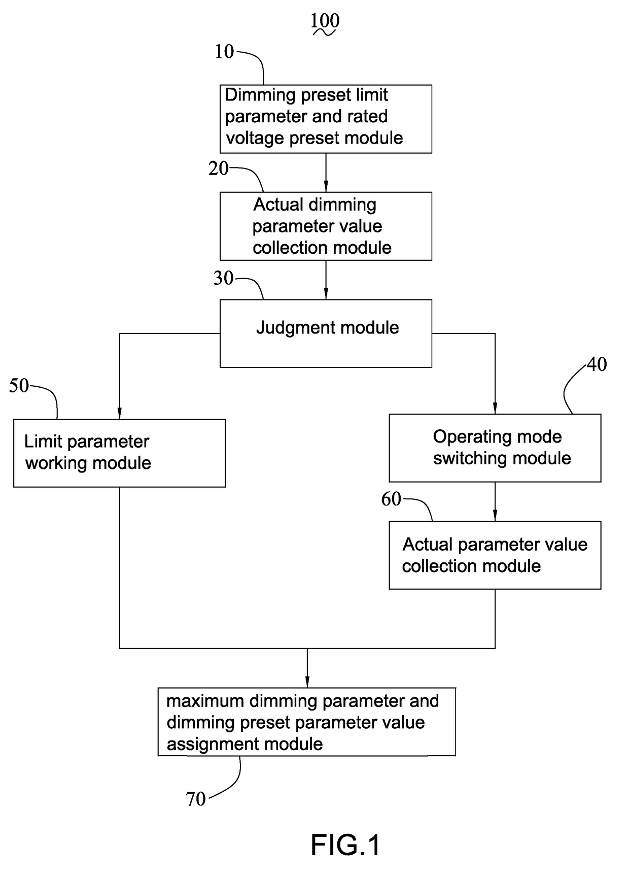
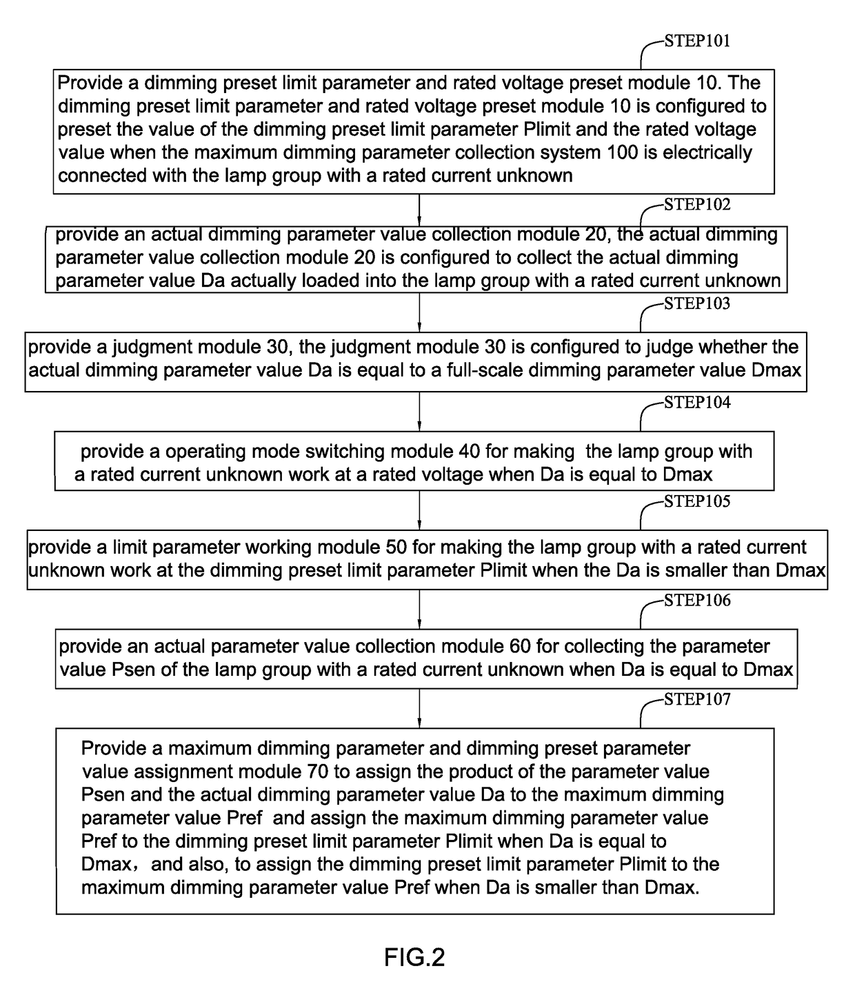
[0020]Please referring to FIG. 1 to FIG. 2, which are a schematic block diagram of the system for collecting maximum dimming parameters of a lamp group with a rated current unknown provided by the present invention. The system for collecting maximum dimming parameters of a lamp group with a rated current unknown comprises a dimming limit parameter and the rated voltage preset module 10, an actual dimming parameter value collection module 20, a judgment module 30, a operating mode switch module 40, a limit parameter working module 50, an actual parameter value collection module 60, and a maximum dimming parameter and a dimming preset parameter value assignment module 70. It is conceivable that the system 100 for collecting the maximum dimming pa...


PUM


Abstract

A system and method for collecting maximum dimming parameters of a lamp group with an unknown rated current includes a lamp operating at a constant voltage or a plurality of lamps connected in parallel. A dimming preset limit parameter and rated voltage preset module, an actual parameter value collecting module, a judgment module, an operating mode switching module, a limit parameter working module, an actual dimming parameter value collecting module, and a maximum dimming parameter and dimming preset parameter value assignment module are present. The system can timely collect the maximum dimming parameter value of the lamp group with a variable or unknown rated current, dimming is effective at any time in the full-scale range, and the dead zone phenomenon if the dimming parameter value is greater than the dimming range of 70% or 50% is reduced.

Description

CROSS-REFERENCE TO A RELATED APPLICATION[0001]This application claims priority to a Chinese Patent Application No. CN 201710738725.4, filed on Aug. 25, 2017.FIELD OF THE TECHNOLOGY[0002]The present invention relates to the power supply for LED lamps, with particular emphasis on a system and method for collecting maximum dimming parameters of a lamp group with a rated current unknown.BACKGROUND[0003]In everyday life, you can see all kinds of lighting equipment everywhere, for examples, fluorescent lamps, street lamps, table lamps, art lamps and so on. All above of the lighting equipment, the tungsten filament bulb has been traditionally used as a light source for illumination. In recent years, the light-emitting diode (LED) has been utilized as light-emitting sources due to the rapid advances in technology. In addition to lighting equipment, the light source of general traffic signs, billboards, Headlights and the like are also replaced by light-emitting diodes. As mentioned above, t...

Claims


Application Information

Patent Timeline
Patent Type & Authority Applications(United States)
IPC IPC(8): H05B33/08H05B44/00
CPCH05B33/0845H05B45/10
Inventor WU, DONG
Owner SELF ELECTRONICS CO LTD
Why Eureka
Eureka Blog
Learn More