Distributed measurement of minimum and maximum in-situ stress in substrates

a technology of in-situ stress and distribution measurement, which is applied in the direction of force measurement by measuring optical property variation, survey, borehole/well accessories, etc., can solve the problems of human-induced seismicity, insufficient understanding of subsurface stress, and combined effects of permeability

Active Publication Date: 2019-02-28
TENNESSEE TECHNOLOGICAL UNIVERSITY +1
View PDF14 Cites 15 Cited by
  • Summary
  • Abstract
  • Description
  • Claims
  • Application Information

AI Technical Summary

Benefits of technology

The patent text discusses the need for better understanding of how subsurface stress and human-induced seismicity affect the permeability of rocks. This is important for the design of wells and other structures, as well as for predicting and preventing rock bursts and managing the flow of fluids and gases in underground formations. The invention described in the patent aims to provide more accurate and precise sensing of stress across a wide range of scales and depths, which can help improve the design of subterranean infrastructure and lead to safer and more cost-effective operations.

Problems solved by technology

Presently, there is insufficient understanding of subsurface stress, human-induced seismicity, and their combined effects on permeability.

Method used


Image

  • Distributed measurement of minimum and maximum in-situ stress in substrates
  • Distributed measurement of minimum and maximum in-situ stress in substrates
  • Distributed measurement of minimum and maximum in-situ stress in substrates

Examples


Embodiment Construction

[0036]In the following description, for purposes of explanation and non-limitation, specific details are set forth, such as particular structures, nodes, functional entities, techniques, etc. in order to provide an understanding of the described technology. It will be apparent to one skilled in the art that other embodiments may be practiced apart from the specific details described below. In other instances, detailed descriptions of well-known methods, devices, techniques, etc. are omitted so as not to obscure the description with unnecessary detail.

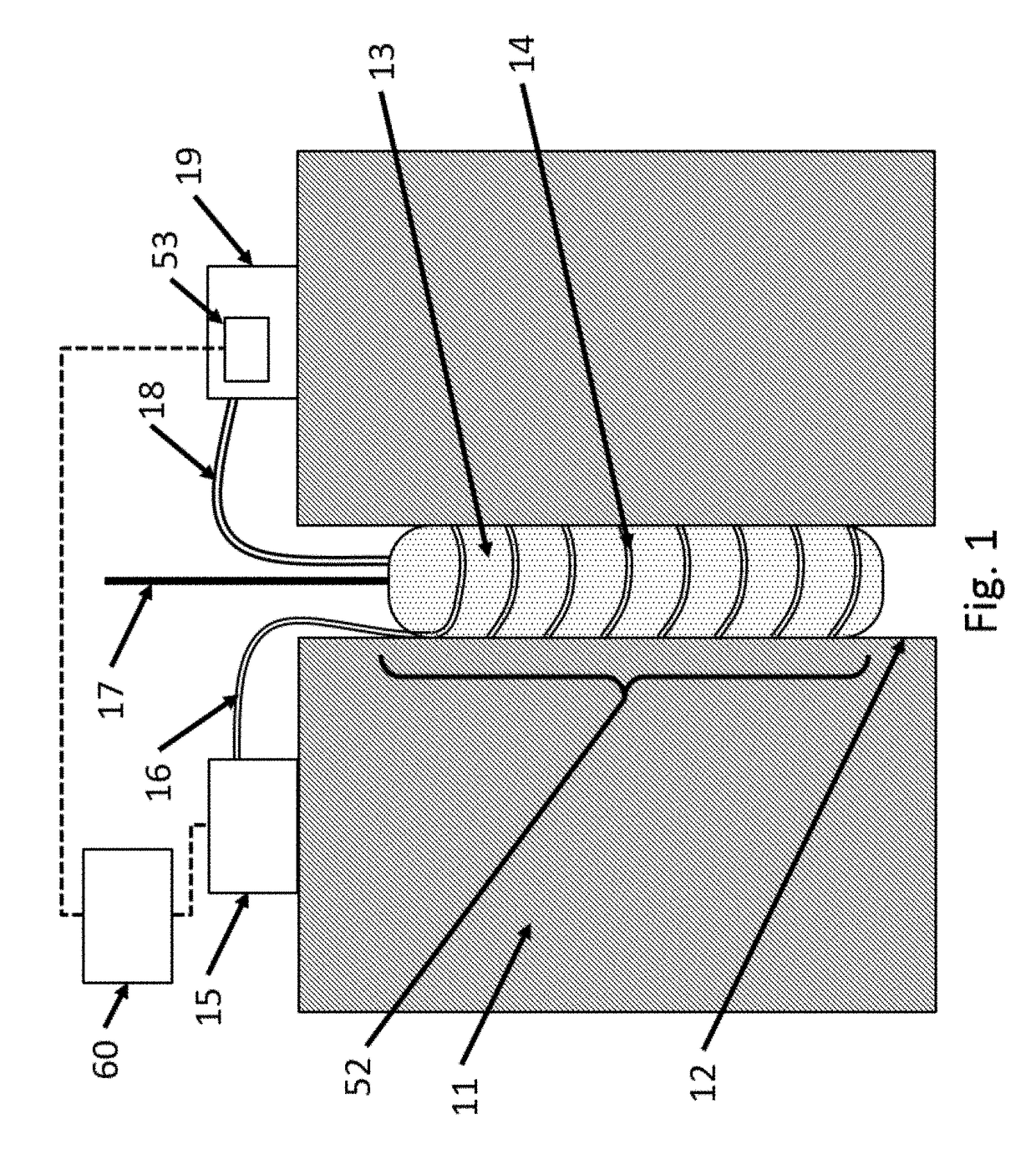
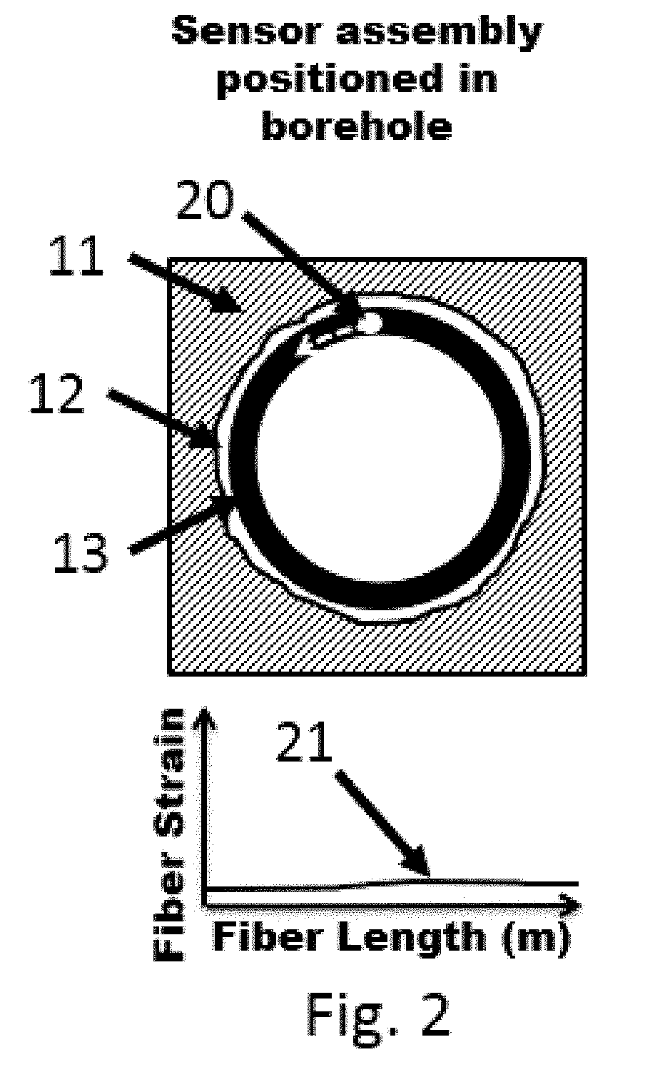
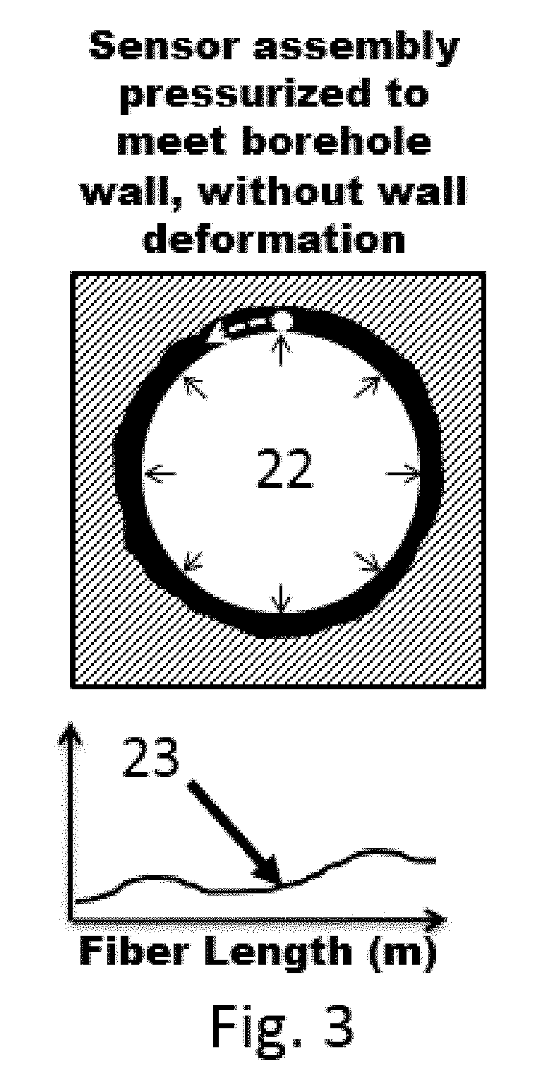
[0037]The example apparatus and methods described herein provide for measuring in-situ stress in a substrate via a hole, e.g., a borehole. In-situ stress is the stress state of the substrate before a hole is made in the substrate. Example embodiments incorporate a distributed fiber optic strain sensor integrated with an expandable element that can apply pressure to the hole wall. The fiber optic sensor can be used to monitor expandable ...


PUM


Abstract

A system for performing distributed measurements of in-situ stress includes an expandable element with at least one fiber optic sensor. The expandable element can be positioned at various depths in a hole in a substrate. A pressurizing device expands (and contracts) the expandable element when the expandable element is inserted in the hole in the substrate to exert pressure on the hole wall. A pressure sensor provides a sensor output indicative of a pressure applied to the hole wall by the expandable element. The fiber optic sensor and an optical interrogator measure strain along a length of the sensor in a continuous, high spatial resolution manner Based on the measured strain and pressure sensor output, the system determines various properties of the substrate such as, minimum principal stress, maximum principal stress, and / or principal stress direction associated with one or more fractures in the substrate, as well as substrate modulus.

Description

CROSS-REFERENCES TO RELATED APPLICATIONS[0001]This application claims priority from U.S. provisional patent application 62 / 551,419, filed on Aug. 29, 2017, the contents of which are incorporated herein by reference.STATEMENT REGARDING FEDERALLY SPONSORED RESEARCH OR DEVELOPMENT[0002]This invention was made with government support under contract DE-SC0015129 awarded by the Department of Energy. The government has certain rights in the invention.TECHNICAL OVERVIEW[0003]The technology described in this application relates to in-situ stress measurements of a substrate. More particularly, the technology described herein relates to high-definition fiber optic sensing technology that provides high spatial resolution strain measurements necessary to determine the in-situ stress in the substrate.INTRODUCTION[0004]A substrate is defined as a solid structure of sufficient thickness and hardness that it develops fractures when placed under sufficient pressure or force. Examples of a substrate a...

Claims


Application Information

Patent Timeline
IPC IPC(8): G01V8/16E21B47/06G01L1/24G01N21/47
CPCG01V8/16E21B47/06G01L1/243G01N21/47G01N2021/4735E21B49/006E21B47/135
Inventor OHANIAN, III, OSGAR JOHNVANDENBERGE, DANIEL R.DAVIS, MATTHEW ANTHONY
Owner TENNESSEE TECHNOLOGICAL UNIVERSITY
Why Eureka
Try Eureka