Dynamically determining origin and destination locations for a network system

a network system and origin and destination technology, applied in the field of selecting a vehicle and a route, can solve the problems of vehicle encountering significant delays during service, and achieve the effect of reducing the number of possible waypoint permutations

Active Publication Date: 2019-01-31
UBER TECH INC
View PDF0 Cites 21 Cited by
  • Summary
  • Abstract
  • Description
  • Claims
  • Application Information

AI Technical Summary

Benefits of technology

[0009]The dynamic routing engine further reduces the number of possible waypoint permutations by applying a haversine ratio filter on the waypoint permutations. The haversine ratio filter is applied to waypoint permutations for active service providers that, with the addition of the new service request, would be satisfying multiple service requests. The dynamic routing engine first determines the sum of the haversine distances between the origin and destination waypoints for each service request of the active service provider. The dynamic routing engine then determines the sum of the haversine distances from each waypoint to the next waypoint in the permutation. The dynamic routing engine then calculates a ratio of each permutation distance to the individual distances and eliminates all permutations that do not have an associated ratio less than a threshold fraction of the individual distance sum.

Problems solved by technology

Depending on the start and end locations provided to the vehicle, the vehicle may encounter significant delays during service between the start and end locations based on the surrounding road topology, traffic conditions, safety concerns, or other factors.
A single plan is generated for an inactive service provider, as there is only one acceptable permutation of a two waypoint plan (going to a requested destination before a requested origin is unacceptable).

Method used


Image

  • Dynamically determining origin and destination locations for a network system
  • Dynamically determining origin and destination locations for a network system
  • Dynamically determining origin and destination locations for a network system

Examples


Embodiment Construction

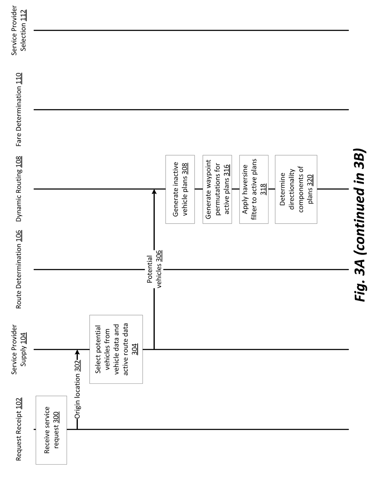
[0038]One use case we explore here for purposes of illustrating various embodiments involves a network system using automobiles. Specifically, drivers and passengers utilizing applications installed on mobile computation devices to communicate with the network system. Passengers use their mobile devices to request service from origin locations to destination locations and the network system notifies drivers that are available to accept the request. A driver then accepts the request using an application on their mobile device and provides the service as requested. Other use cases exist—in general, any application in which vehicles are used to perform services relating to people or objects—and the particular examples that flow throughout this description should be understood to be given for ease of illustration, and not as a limitation of scope.

[0039]Considering the example of a network system, typically when a request is made by a service requester (e.g., a passenger) for a service f...


PUM


Abstract

A network system dynamically determines a route, including start and end points, for vehicles in a transportation network. The transportation network receives a service request from a user of the transportation network including an origin location for the trip and a destination location for the trip. The transportation network then generates a waypoint plan for one or more vehicles, which includes the requested origin and destination in addition to any previously requested origins and destinations included in the vehicles current route. The network system then determines a directionality for each of the waypoints in the waypoint plan and retrieves candidate start and end points that have an associated directionality within a threshold angle of the directionality of each waypoint and are proximate to the waypoint. The network system evaluates each combination of retrieved candidate points to select a route for the vehicle.

Description

BACKGROUNDField[0001]The described embodiments relate generally to providing vehicle routing guidance to dynamically determined start and end locations, and more particularly to selecting a vehicle and route based on the dynamically determined points.Description of Related Art[0002]On-demand network systems allow users to request services from one location to another, such as transportation of people or delivery of an object from an origin location to a destination location. A network system typically selects a vehicle from amongst a network of vehicles to transport a requesting user or a requested object from the origin location to the destination location. Typically, one or more vehicles are selected to provide services based on the relative location of the vehicles to the origin location of the request or based on a current route of a vehicle that is proximate to the origin location and destination location. A network system may then determine a new route that includes a path fro...

Claims


Application Information

Patent Timeline
Patent Type & Authority Applications(United States)
IPC IPC(8): G01C21/34G01C21/36G06Q50/30G06Q10/06
CPCG01C21/3438G01C21/362G01C21/3415G06Q10/06315G06Q50/30G06Q10/02G06Q10/047G01C21/3423
Inventor CHEN, QILAWLER, CASEYSHI, LINFENGXU, QINGYU, MIAO
Owner UBER TECH INC
Why Eureka
Try Eureka