
Generation method for multi-view auto-stereoscopic images, displaying method and electronic apparatus

a multi-view, auto-stereoscopic technology, applied in stereoscopic photography, instruments, optics, etc., can solve the problems of increasing the number of cameras, reducing the utility of the display device, and reducing the cost and image processing time of the equipment, so as to save equipment cost and image processing time, effectively present the stereoscopic image, and improve the effect of photographing

Inactive Publication Date: 2019-01-24
THEIA
View PDF0 Cites 3 Cited by
  • Summary
  • Abstract
  • Description
  • Claims
  • Application Information

AI Technical Summary

Benefits of technology

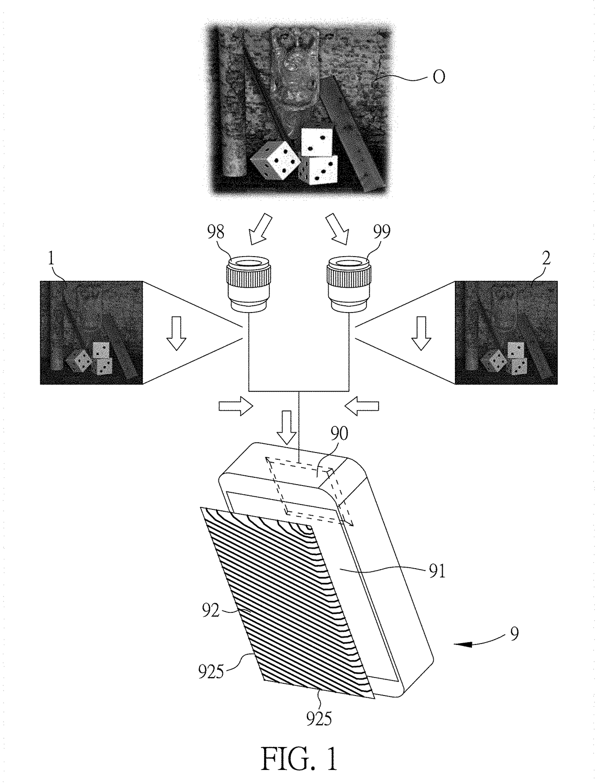
The invention provides a method for generating a multi-view auto-stereoscopic image using only one image capturing device and the computed disparity information. This saves equipment cost and image-processing time and improves convenience in photographing. The method also allows for interlacing and displaying the image on a display device with an oblique lenticular lens layer, which improves the utility of the display device.

Problems solved by technology

As number of the viewpoints increases, the number of required cameras increases, which raises cost and image-processing time.
That is, if the cameras are configured along orientations other than the orientation from the left eye to the right eye, a disparity information resulted from the captured views cannot be comprehended by the brain for conceiving stereoscopic impression, which restricts utility of the display device.
Since the segmentation direction needs to be parallel to the orientation of the lenticular lenses so as to properly refract the interlaced image to the eyes, it is concluded that the conventional display device is restricted to a portrait displaying mode for the eyes to perceive the refracted interlaced image properly, which is also unfavorable to the utility of the display device.

Method used


Image

  • Generation method for multi-view auto-stereoscopic images, displaying method and electronic apparatus
  • Generation method for multi-view auto-stereoscopic images, displaying method and electronic apparatus
  • Generation method for multi-view auto-stereoscopic images, displaying method and electronic apparatus

Examples


Embodiment Construction

[0045]Certain terms are used throughout the following description and claims to refer to particular system components. As one skilled in the art will appreciate, manufacturers may refer to a component by different names. In the following discussion and claims, the system components are differentiated not by their names but by their function and structure differences. In the following discussion and claims, the terms “include” and “comprise” are used in an open-ended fashion and should be interpreted as “include but is not limited to”. Also, the term “couple” or “link” is intended to mean either an indirect or a direct mechanical or electrical connection. Thus, if a first device is coupled or linked to a second device, that connection may be through a direct mechanical or electrical connection, or through an indirect mechanical or electrical connection via other devices and connections.

[0046]In the following detailed description of the preferred embodiments, reference is made to the ...


PUM


Abstract

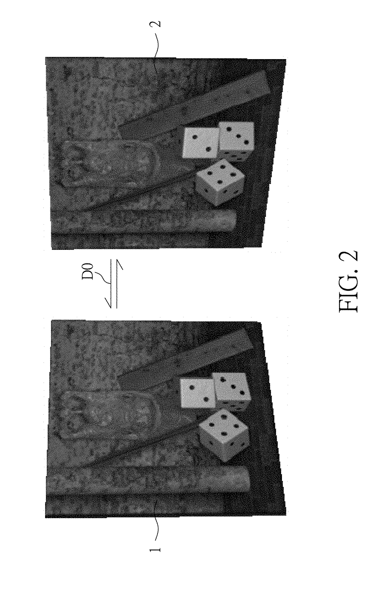
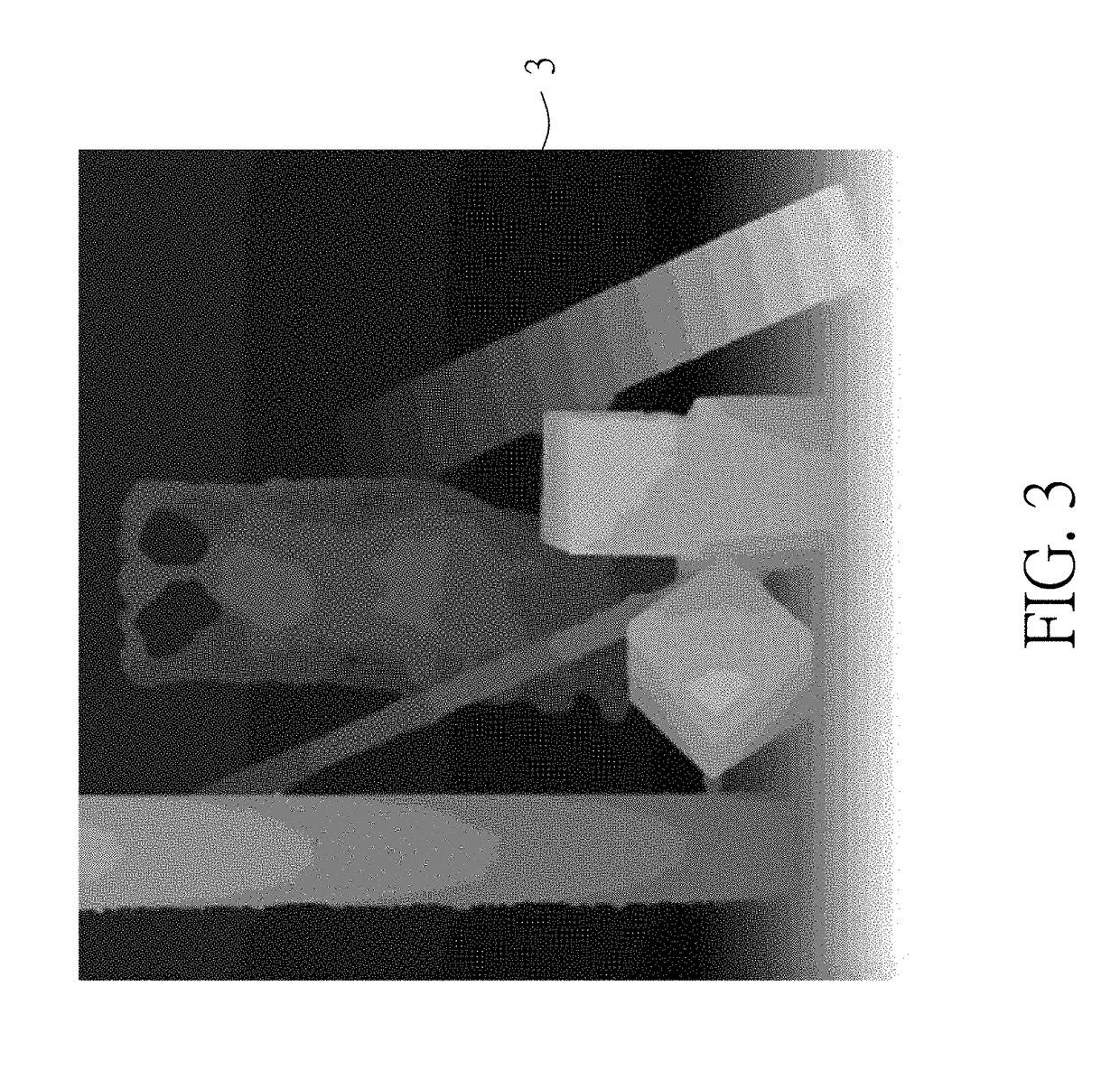
The generation method for a multi-view auto stereoscopic image of the present invention calculates a disparity between a first view and a second view captured from a certain scene and disregards the second view. A processing unit utilizes merely the first view and the disparity to generate, via a loop mode algorithm, a plurality of disparity images suitable for synthesizing a stereoscopic image, which allows the first view and the second view to be captured at any angle. Furthermore, the displaying method and the corresponding electronic apparatus of the present invention obliquely segment the disparity images before an interlacing process and display the interlaced image via a compatible tilted lenticular lens layer, which allows the displaying apparatus to present effective stereoscopic effect at any angle. Therefore, the present application not only reduces implementation cost and image processing time but also improves convenience and versatility for shooting and viewing.

Description

CROSS REFERENCE TO RELATED APPLICATIONS[0001]This invention claims the benefit of US Provisional Patent Application No. 62 / 535,239, filed on Jul. 21, 2017, which is hereby incorporated by reference in its entirety.BACKGROUND OF THE INVENTION1. Field of the Invention[0002]The invention relates to a generation method for a stereoscopic image, a displaying method and an electronic apparatus, and more particularly, to a generation method for a multi-view auto-stereoscopic image, a displaying method and an electronic apparatus.2. Description of the Prior Art[0003]When human eyes view an object, the left eye and the right eye respectively capture views of the same object, wherein a disparity exists between the image captured by the left eye and the image captured by the right eye, and thereby the brain is able to fuse the images captured by the left and right eyes to form a stereoscopic image based on the disparity.[0004]Conventional generation method for an auto-stereoscopic image and a ...

Claims


Application Information

Patent Timeline
Patent Type & Authority Applications(United States)
IPC IPC(8): H04N13/351H04N13/305H04N13/32H04N13/315H04N13/354G03B35/08
CPCH04N13/351H04N13/305H04N13/32H04N13/315H04N13/354G03B35/08G02B30/27H04N13/282H04N13/111H04N13/271H04N13/268H04N13/239
Inventor LIN, YU-HSUANPO, TANG-HUNG
Owner THEIA
Learn More