
Painting Tool

a technology of painting tools and cutting boards, applied in the field of painting tools, can solve the problems of user scratching fingers, inconvenience in use, etc., and achieve the effect of convenient and reliable coupling and removal, and easy replacement of the knife board

Inactive Publication Date: 2019-01-24
HUANG CHIN CHEN
View PDF30 Cites 4 Cited by
  • Summary
  • Abstract
  • Description
  • Claims
  • Application Information

AI Technical Summary

Benefits of technology

The present invention aims to solve issues by providing a painting tool with a detachable knife board that is easy to replace. Additionally, the tool has a comfortable grip for the user, making it easy to operate.

Problems solved by technology

Since the screws are apt to become loosened after a period of time of use, the screws must be retightened, which is inconvenience in use.
However, the small angle also easily causes the fingers of the user to be in frictional contact with the wall surface or the ground, leading to scratched fingers of the user.

Method used


Image

  • Painting Tool
  • Painting Tool
  • Painting Tool

Examples


Embodiment Construction

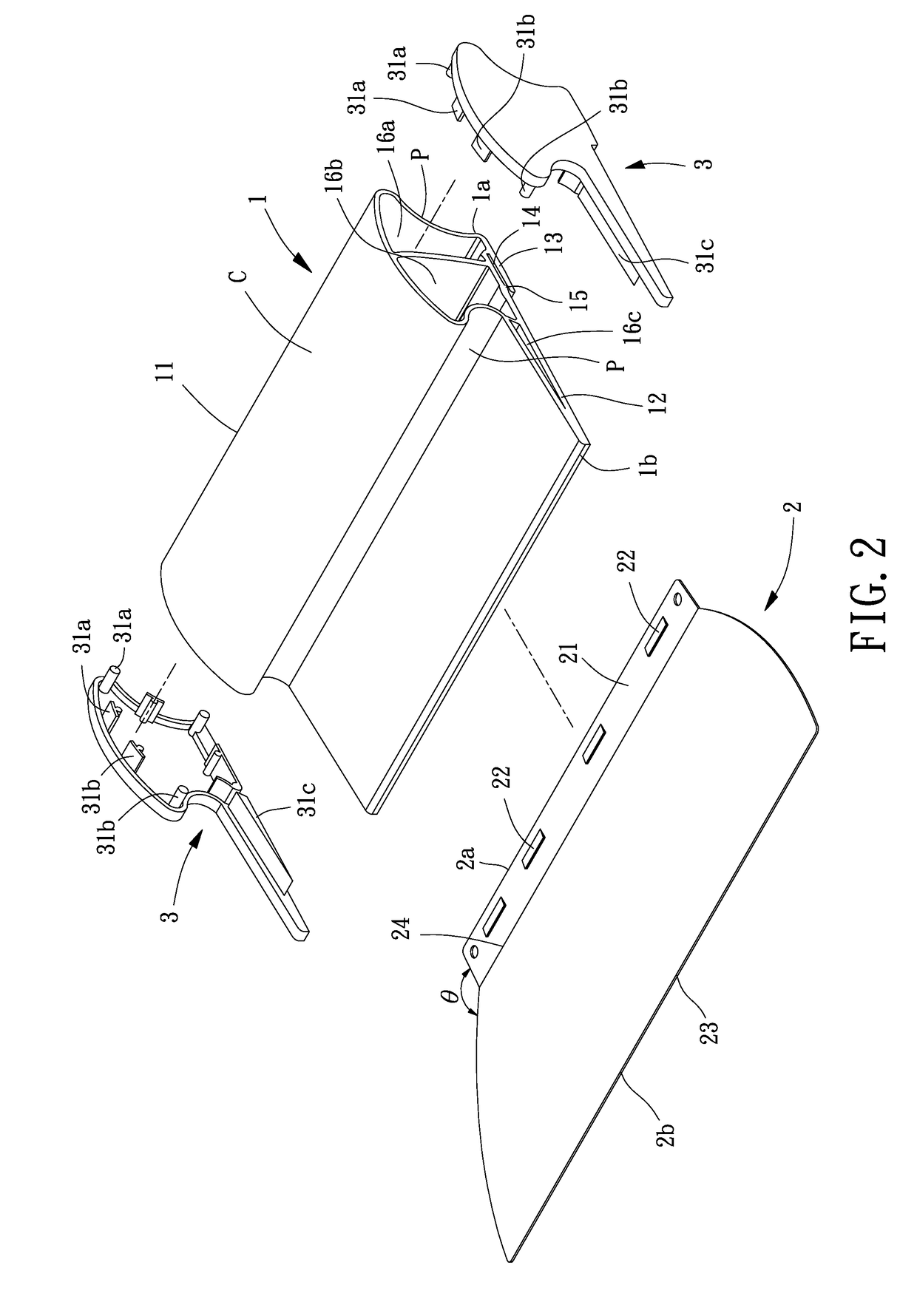
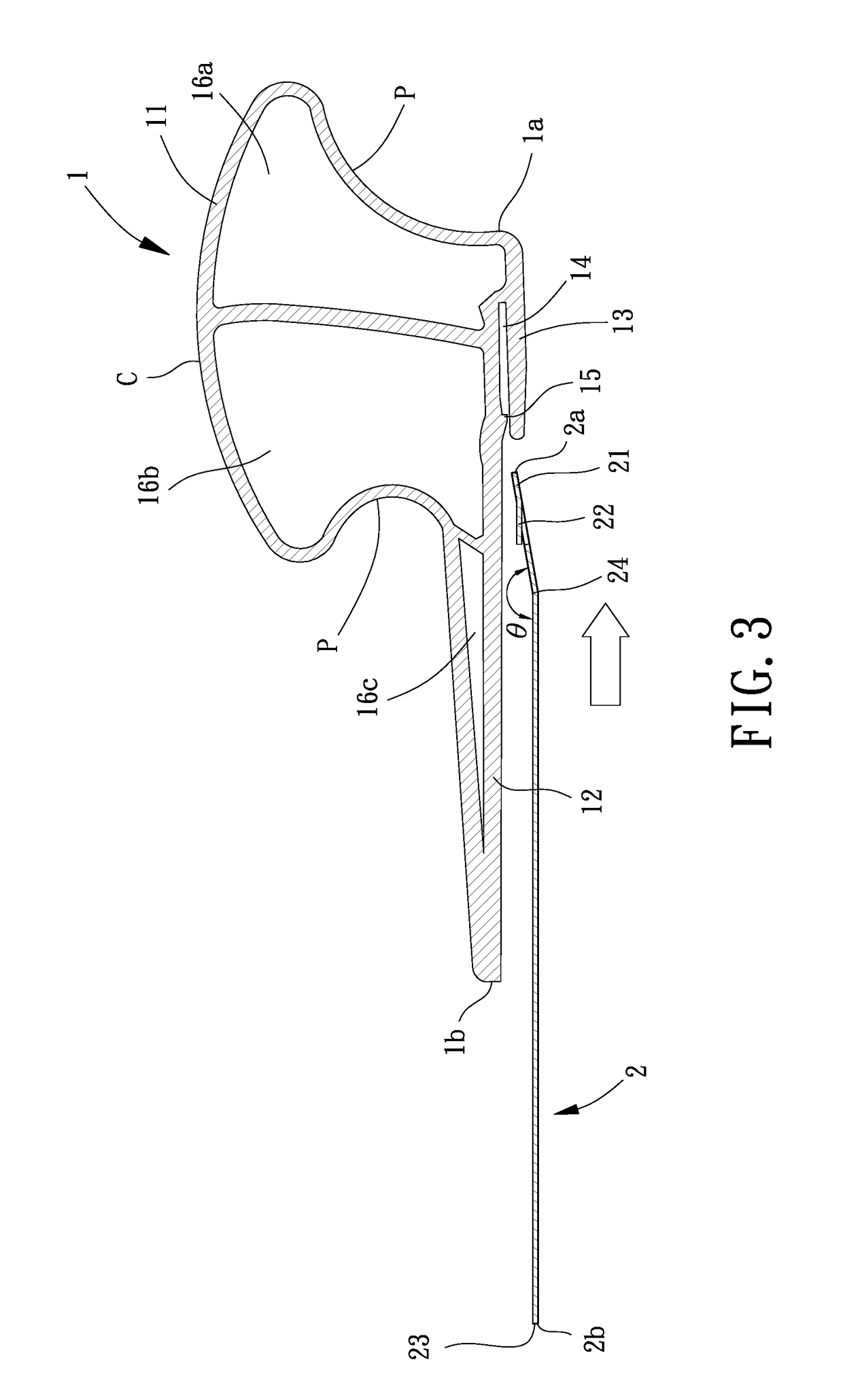
[0026]With reference to FIGS. 2 and 3, a painting tool of an embodiment according to the present invention includes a body 1 and a knife board 2. The knife board 2 can be easily coupled with a coupling groove 14 of the body 1 and can be removed out of the coupling groove 14.

[0027]The body 1 includes a gripping portion 11, an abutting portion 12, and a projecting board 13. The gripping portion 11 is located on a first side 1a of the body 1 and protrudes from an upper surface of the body 1. Preferably, the cross sectional area of a top portion of the gripping portion 11 is larger than the cross sectional area of a bottom portion of the gripping portion 11, permitting easy gripping of the body 1 by a user. Preferably, the top portion of the gripping portion 11 includes an arcuate surface C. Furthermore, the gripping portion 11 includes two lateral sides extending between the top portion and the bottom portion of the gripping portion 11. Each of the two lateral sides includes a recessed...


PUM


Abstract

A painting tool includes a body having a gripping portion, an abutting portion, and a projecting board. The gripping portion is located on a first side of the body and protrudes from an upper surface of the body. The abutting portion is formed on a bottom surface of the body and protrudes from a bottom of the gripping portion toward a second side of the body. The projecting board protrudes from the bottom surface of the gripping portion toward the second side of the body. A coupling groove is defined between the projecting board and the abutting portion and has an opening facing the second side of the body. A knife board includes a first side having a coupling portion coupled with the coupling groove. A levelling portion is formed on a second side of the knife board.

Description

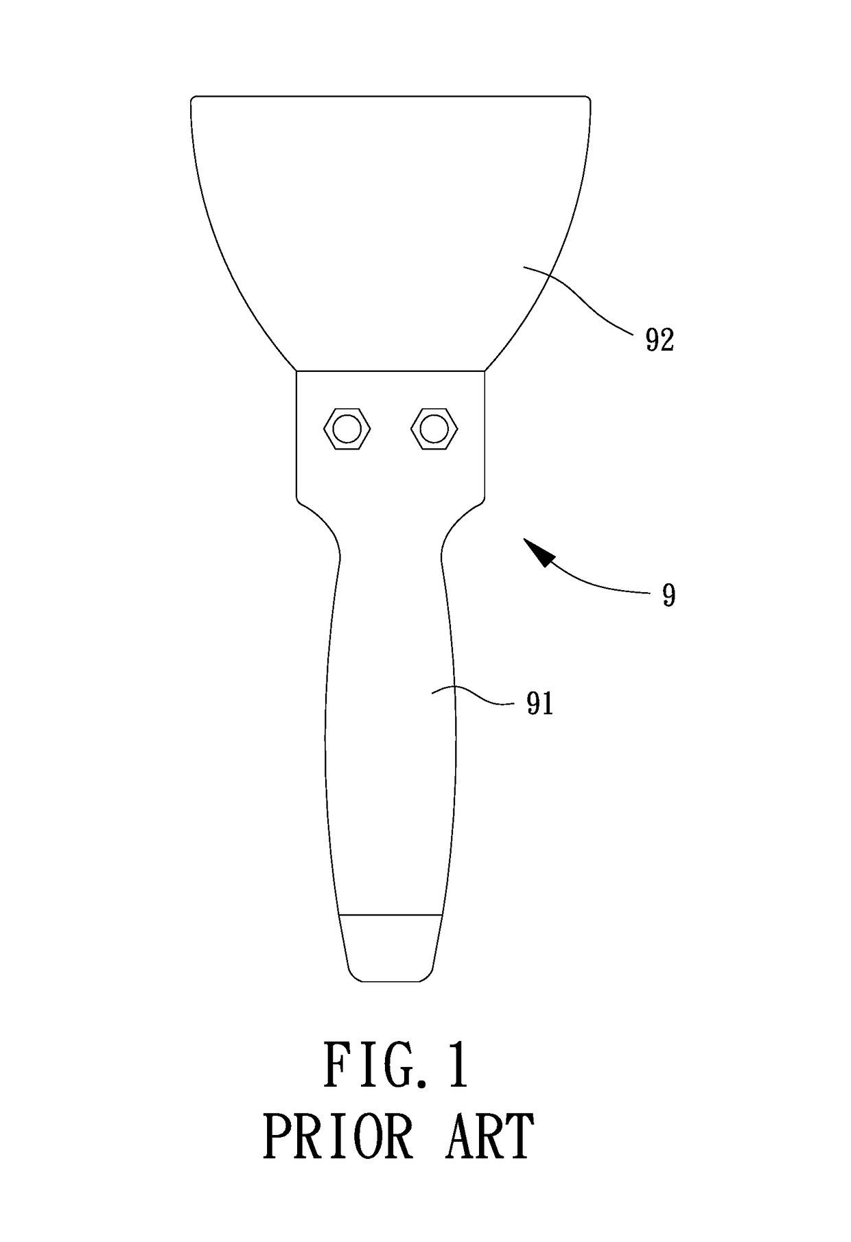
BACKGROUND OF THE INVENTION1. Field of the Invention[0001]The present invention relates to a painting tool and, more particularly, to a painting tool that is easy to disassemble and that is easy to grip.2. Description of the Related Art[0002]FIG. 1 shows a conventional scraper 9 for painting. The conventional scraper 9 is used to level a wall surface to be painted. The conventional scarper 9 includes a handle 91 and a knife board 92 fixed to the handle 91 by screws. When replacement of the knife board 92 is required, a wrench or a screwdriver is required to remove the screws for removing the knife board 92 and subsequent assembly of a new knife board 92. Since the screws are apt to become loosened after a period of time of use, the screws must be retightened, which is inconvenience in use.[0003]Furthermore, when using the conventional scraper 9, a user has to hold the handle 91 to keep the knife board 92 at an inclination angle to the wall surface or the ground for removing protrusi...

Claims


Application Information

Patent Timeline
Patent Type & Authority Applications(United States)
IPC IPC(8): E04F21/02B08B1/00
CPCB08B1/005E04F21/026E04F21/163B08B1/165
Inventor HUANG, CHIN-CHEN
Owner HUANG CHIN CHEN
Learn More