
Dynamic calibration systems and methods for wearable heads-up displays

a head-up display and calibration system technology, applied in the field can solve the problems of not being able to see the external environment of users, the majority of wearable heads-up displays presented to date are considerably bulkier and less stylish than conventional eyeglass frames, and achieve accurate gaze location detection, minimize similarity, and maximize the respective distance

Inactive Publication Date: 2019-01-17
GOOGLE LLC
View PDF15 Cites 4 Cited by
  • Summary
  • Abstract
  • Description
  • Claims
  • Application Information

AI Technical Summary

Benefits of technology

The patent describes a method for displaying user interface elements on a wearable heads-up display device. The device detects the user's gaze and uses that information to determine which part of the display they are looking at. The device then displays one or more UI elements on the screen. The method ensures that the UI elements are positioned at a safe distance from each other and that they are easier to see. The result is a more efficient and effective way of displaying information on a wearable device that is comfortable for the user to read.

Problems solved by technology

A wearable heads-up display is a head-mounted display that enables the user to see displayed content but also does not prevent the user from being able to see their external environment.
Independent of their performance limitations, many of the aforementioned examples of wearable heads-up displays have struggled to find traction in consumer markets because, at least in part, they lack fashion appeal.
Most wearable heads-up displays presented to date employ large display components and, as a result, most wearable heads-up displays presented to date are considerably bulkier and less stylish than conventional eyeglass frames.
A challenge in the design of wearable heads-up displays is to minimize the bulk of the face-worn apparatus while still providing displayed content with sufficient visual quality.

Method used


Image

  • Dynamic calibration systems and methods for wearable heads-up displays
  • Dynamic calibration systems and methods for wearable heads-up displays
  • Dynamic calibration systems and methods for wearable heads-up displays

Examples


Embodiment Construction

[0051]In the following description, certain specific details are set forth in order to provide a thorough understanding of various disclosed implementations. However, one skilled in the relevant art will recognize that implementations may be practiced without one or more of these specific details, or with other methods, components, materials, etc. In other instances, well-known structures associated with computer systems, server computers, and / or communications networks have not been shown or described in detail to avoid unnecessarily obscuring descriptions of the implementations.

[0052]Unless the context requires otherwise, throughout the specification and claims that follow, the word “comprising” is synonymous with “including,” and is inclusive or open-ended (i.e., does not exclude additional, unrecited elements or method acts).

[0053]Reference throughout this specification to “one implementation” or “an implementation” means that a particular feature, structure or characteristic de...


PUM


Abstract

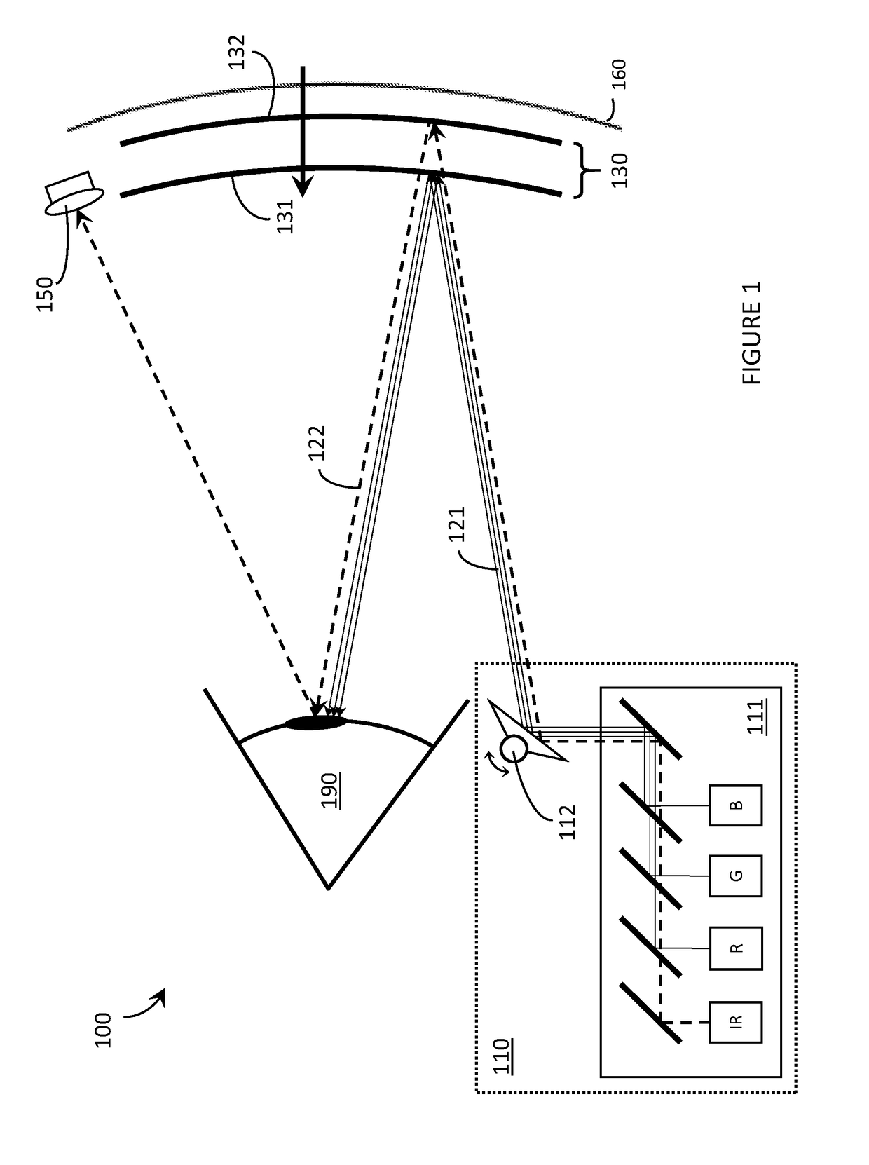
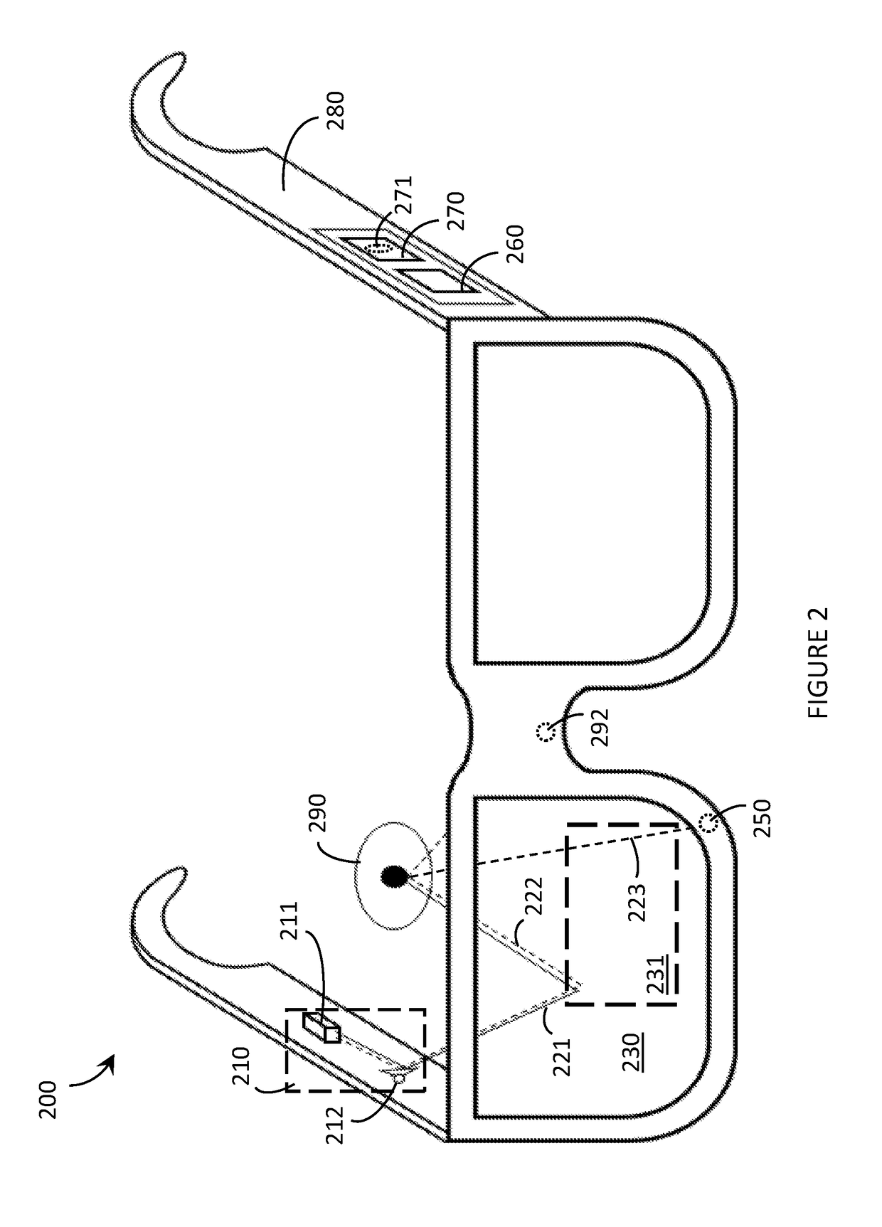
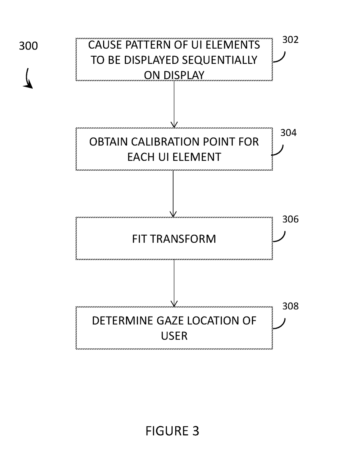
Systems, methods and articles that provide dynamic calibration of eye tracking systems for wearable heads-up displays (WHUDs). The eye tracking system may determine a user's gaze location on a display of the WHUD utilizing a calibration point model that includes a plurality of calibration points. During regular use of the WHUD by the user, the calibration point model may be dynamically updated based on the user's interaction with user interface (UI) elements presented on the display. The UI elements may be specifically designed (e.g., shaped, positioned, displaced) to provide in-use and on-going dynamic calibration of the eye tracking system, which in at least some implementations may be unnoticeable to the user.

Description

BACKGROUNDTechnical Field[0001]The present disclosure generally relates to wearable heads-up displays, and more particularly, to calibration systems and methods for eye tracking systems of wearable heads-up displays.Description of the Related Art[0002]Wearable Heads-Up Displays[0003]A head-mounted display is an electronic device that is worn on a user's head and, when so worn, secures at least one electronic display within a viewable field of at least one of the user's eyes, regardless of the position or orientation of the user's head. A wearable heads-up display is a head-mounted display that enables the user to see displayed content but also does not prevent the user from being able to see their external environment. The “display” component of a wearable heads-up display is either transparent or at a periphery of the user's field of view so that it does not completely block the user from being able to see their external environment. Examples of wearable heads-up displays include: ...

Claims


Application Information

Patent Timeline
Patent Type & Authority Applications(United States)
IPC IPC(8): G06F3/01G09G5/37G02B27/01G06V40/19
CPCG06F3/013G09G5/37G02B27/0172G02B2027/0174G09G2354/00G02B2027/0178G02B2027/014G09G2340/0464G06F3/147G09G3/002G09G2320/0693G09G2370/022G02B27/017G02B2027/0187G06V40/19G02B27/0093G02B27/0179G06T13/80
Inventor ALEEM, IDRIS S.BHARGAVA, MAYANKJACOBS, DYLAN
Owner GOOGLE LLC
Learn More