Press machine
a press machine and machine body technology, applied in the field of press machines, can solve problems such as reducing workability, and achieve the effects of reducing the stress on the operator, accurately controlling, and reliably matching each other
- Summary
- Abstract
- Description
- Claims
- Application Information
AI Technical Summary
Benefits of technology
Problems solved by technology
Method used
Image
Examples
second preferred embodiment
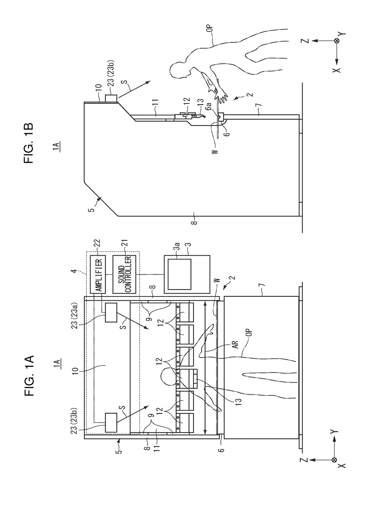
[0059]A second preferred embodiment of the present invention will be described. In the present preferred embodiment, elements similar to those of the above preferred embodiment are given the same reference signs and description thereof will be omitted or simplified. FIGS. 5A and 5B include drawings showing a press machine 1B of the second preferred embodiment. A sound controller 21 of the press machine 1B notifies an operator OP of the side on which machining will be performed, of a machining region AR of a machine body 2 by controlling the direction in which a sound S is outputted from speakers 23. The sound controller 21 controls the direction in which a sound S is outputted from the speakers 23 by outputting the sound S selectively from speakers 23a, 23b on both sides.
[0060]For the convenience of description, it is assumed that the current machining is performed on the positive Y-side of the machining region AR and the subsequent machining is performed on the negative Y-side afte...
third preferred embodiment
[0063]A third preferred embodiment of the present invention will be described. In the present preferred embodiment, elements similar to those of the above preferred embodiments are given the same reference signs and description thereof will be omitted or simplified. FIG. 6 is a drawing showing a press machine of the third preferred embodiment.
[0064]In a press machine 1C of the present preferred embodiment, a notifier 4 includes a sensor 28 that detects the operation of a machine body 2. For example, the sensor 28 detects the position information (e.g., position, speed, acceleration) of a ram 11. The sensor 28 is connected to a body controller 3 so as to be able to communicate therewith and supplies the detection result to the body controller 3.
[0065]The body controller 3 controls the position of the ram 11 on the basis of the detection result of the sensor 28. The body controller 3 also determines in which of a series of machining stages the current operation of the machine body 2 i...
fourth preferred embodiment
[0067]A fourth preferred embodiment of the present invention will be described. In the present preferred embodiment, elements similar to those of the above preferred embodiments are given the same reference signs and description thereof will be omitted or simplified. FIG. 7 is a drawing showing a press machine 1D of the fourth preferred embodiment.
[0068]In the press machine 1D, a notifier 4 includes a display 29. The notifier 4 notifies an operator OP of the operation of a machine body 2 or the state of a workpiece W in advance by displaying an image showing the operation of the machine body 2 or the state of the workpiece W on the display 29. The notifier 4 displays the image on the display 29 in synchronization with the output of at least one of a sound and light. The display 29 is disposed, for example, on a ram 11, but may be disposed in another location. The display 29 may be a part of the notifier 4 or may be a part of a device other than the notifier 4. For example, the notif...
PUM
| Property | Measurement | Unit |
|---|---|---|
| frequency | aaaaa | aaaaa |
| stress | aaaaa | aaaaa |
| distance | aaaaa | aaaaa |
Abstract
Description
Claims
Application Information
 - R&D
- Intellectual Property
- Life Sciences
- Materials
- Tech Scout
- Unparalleled Data Quality
- Higher Quality Content
- 60% Fewer Hallucinations
Browse by: Latest US Patents, China's latest patents, Technical Efficacy Thesaurus, Application Domain, Technology Topic, Popular Technical Reports.
© 2025 PatSnap. All rights reserved.Legal|Privacy policy|Modern Slavery Act Transparency Statement|Sitemap|About US| Contact US: help@patsnap.com


