
Droneboarding System With Mechanical Flight Control

Active Publication Date: 2018-12-06
HENRY DAVID EDWARD
View PDF13 Cites 6 Cited by
  • Summary
  • Abstract
  • Description
  • Claims
  • Application Information

AI Technical Summary

Benefits of technology

The present invention provides a mechanism for allowing an individual to mechanically control and influence the flight path of a drone. This is achieved through a system where additional electrical power is delivered to the drone via a remote power supply carried by the individual. The droneboarding system includes a drone and a tension line attachment point on the drone, which can be adjusted to control the flight path of the drone. The system also includes a tow handle for pulling the user over a surface, with tension lines attached to the drone and the handle for mechanical control of the flight path. The user can adjust the tension lines to their desired position to control the drone's behavior. The invention provides a safe and presumable enjoyable experience for droneboarding.

Problems solved by technology

A limitation of kiteboarding is that it is dependent on the wind.
While solving some of the issues inherent in kiteboarding, droneboarding is itself not without challenges.
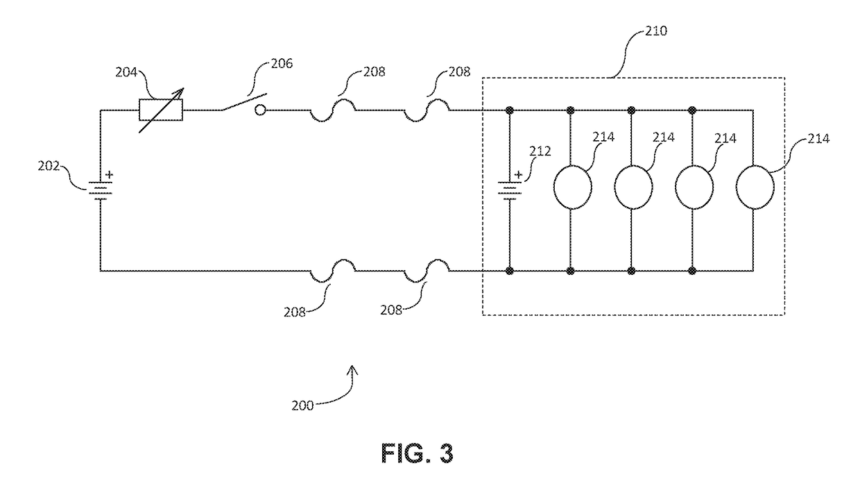
Another challenge inherent in using a drone to pull a droneboarder is providing sufficient power to the drone.
Pulling a human across the water or snow requires a significant amount of power.
Onboard batteries powering a droneboarding drone are quickly depleted.
Increased electrical storage capacity (more batteries) is required to extend the flight time of the drone and prolong the droneboarder's experience; however, increased storage capacity means increased weight, as batteries are heavy.
In general, the larger the storage capacity of a battery, the heavier it is.
At some point, the additional power provided by additional onboard batteries is consumed in getting the additional weight of the extra batteries off the ground.

Method used


Image

  • Droneboarding System With Mechanical Flight Control
  • Droneboarding System With Mechanical Flight Control
  • Droneboarding System With Mechanical Flight Control

Examples


Embodiment Construction

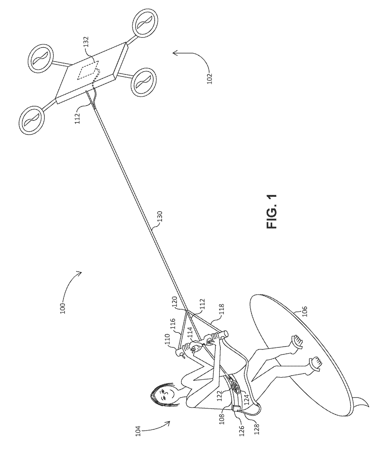
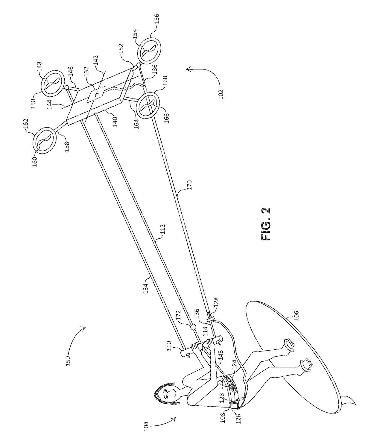
[0025]FIG. 1 shows the basic components of a droneboarding system 100 according to an embodiment of the present invention. The droneboarding system 100 includes an unmanned aerial vehicle (drone) 102 which is used to pull a user 104 riding a board 106 over a surface.

[0026]The drone 102 described herein is representative only. Features of the drone 102, such as the configuration of the drone, the size and number of propellers, the presence of an onboard power source, and the like, will vary depending on the make and model of the selected drone. All that is required of the drone is that it be large enough and have sufficient power to pull the user and the board on which the user is riding over the particular surface the board is adapted to travel. For purposes of the present disclosure, a generic four-propellerquadcopter” is described.

[0027]The board 106 may be a surfboard, a kiteboard, a wakeboard, a snowboard, one or more snow skis or water skis, a skateboard or longboard, or any ...


PUM


Abstract

A droneboarding system is disclosed. The droneboarding system includes an unmanned aerial vehicle (drone) for pulling a droneboarder riding a board over a surface, a harness, a tow handle and a plurality of tension lines. Each tension line is attached to the drone and to either the tow handle or the harness. The tension lines are configured in a manner that provides mechanical control of the flight path of the drone. A remote power supply is adapted to be carried by the droneboarder. One of the tension line carries an electrical conductor from the remote power supply to the drone. The electrical conductor provides electrical power from the remote power supply to the drone.

Description

CROSS-REFERENCE TO RELATED APPLICATIONS[0001]This application is a continuation-in-part of application Ser. No. 15 / 613,218, filed Jun. 4, 2017.BACKGROUND OF THE INVENTION[0002]Droneboarding is a relatively new recreational activity. Droneboarding is similar to the more established sport of kitesurfing, or kiteboarding. In kiteboarding, kiteboarders employ a large kite or sail to pull themselves over some surface, such as the surface of a lake or the ocean or, in colder climes, a snow-covered field. A kiteboarder typically rides a board adapted for the particular surface over which he or she intends to travel. For example, a kiteboarder kiteboarding on the ocean or on a lake may ride a surfboard, a wakeboard, a water ski, or the like; whereas a kiteboarder kiteboarding in the snow may ride a snowboard or skis.[0003]A limitation of kiteboarding is that it is dependent on the wind. On calm days the avid kiteboarder must be content with other activities. Not only is kiteboarding depende...

Claims


Application Information

Patent Timeline
IPC IPC(8): B64C39/02B63B35/79
CPCB64C39/026B64C39/022B64C39/024B63B35/7943B64C2201/042B63B32/10B64U50/19B64U30/20B64U2101/05B64U10/14B64U10/60B64U50/34B63B34/60B63B32/40B64U10/10B64U2101/00
Inventor HENRY, DAVID EDWARD
Owner HENRY DAVID EDWARD
Learn More