
Turbomachine lubricating oil analyzer system, computer program product and related methods

a technology of lubricating oil and analyzer, which is applied in the field of turbomachine systems, can solve the problems of compromising the accuracy of testing, unable to properly monitor others not drawing samples frequently enough to achieve the effect of properly monitoring the condition of oil,

Inactive Publication Date: 2018-11-29
GENERAL ELECTRIC CO
View PDF6 Cites 4 Cited by
  • Summary
  • Abstract
  • Description
  • Claims
  • Application Information

AI Technical Summary

Benefits of technology

The patent describes a system and method for monitoring the life of lubrication oil in a turbomachine. The system can determine the temperature and contamination level of the oil, and using these measurements, calculate the ideal remaining life of the oil. By monitoring these factors, the system can provide an accurate measurement of the oil's actual remaining life. The technical effects are improved monitoring and maintenance of lubrication oil in turbomachines, leading to reduced downtime and improved efficiency.

Problems solved by technology

However, some customers improperly draw the oil samples, which can compromise accuracy of the testing.
Others do not draw samples frequently enough to properly monitor the condition of the oil.
These automotive systems do not, however, test the lubricating oil to determine its quality.
While more modern conventional systems include particular hardware for sampling and analyzing lubrication oil in turbomachinery, that hardware can be costly to procure and maintain.
Further, those hardware-based systems may struggle to accurately assess (e.g., predict) the future quality of lubricating oil in a turbomachine.

Method used


Image

  • Turbomachine lubricating oil analyzer system, computer program product and related methods
  • Turbomachine lubricating oil analyzer system, computer program product and related methods
  • Turbomachine lubricating oil analyzer system, computer program product and related methods

Examples


Embodiment Construction

[0015]As indicated above, the subject matter disclosed herein relates to lubrication oil in turbomachinery. More particularly, the subject matter disclosed herein relates to approaches for analyzing a lubricating oil using test data extracted from that oil, exclusive of measured particle-count data.

[0016]As noted herein, it can be difficult to effectively monitor the quality of lubricating oil in turbomachine systems, which can lead to undesirable degradation of the oil, and ultimately, damage the turbomachine that relies upon that oil for lubrication.

[0017]In contrast to conventional approaches, various embodiments of the disclosure include systems, computer program products and associated methods to analyze a lubricating oil using test data extracted from that oil, exclusive of measured particle-count data. That is, the approaches according to various embodiments of the disclosure are configured to analyze lubricating oil without particle count data measured from that oil. In some...


PUM

PropertyMeasurementUnit
temperatureaaaaaaaaaa
frequencyaaaaaaaaaa
Arrhenius Reaction Rateaaaaaaaaaa

Abstract

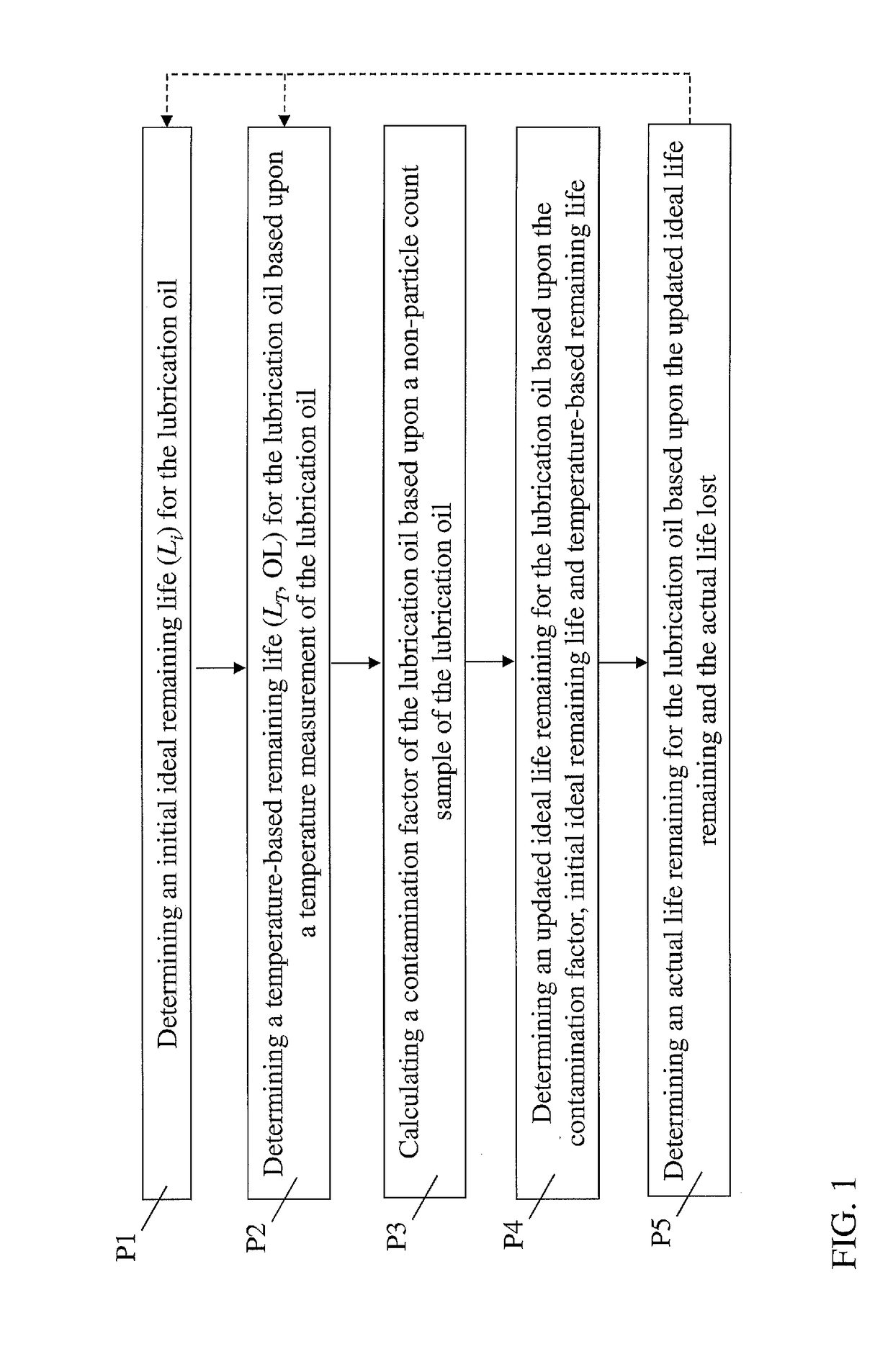
Various embodiments of the invention include a system having: at least one computing device at least one computing device configured to monitor a lubrication oil by performing actions including: determining an initial ideal remaining life for the lubrication oil; determining a temperature-based remaining life for the lubrication oil based upon a temperature measurement of the lubrication oil; calculating a contamination factor of the lubrication oil based upon a non-particle count sample of the lubrication oil; determining an updated ideal life remaining for the lubrication oil based upon the contamination factor, the initial ideal remaining life, and the temperature-based remaining life; and determining an actual life remaining for the lubrication oil based upon the updated ideal life remaining and an actual life lost for the lubrication oil.

Description

FIELD OF THE INVENTION[0001]The subject matter disclosed herein relates to turbomachine systems. More particularly, the subject matter disclosed herein relates to analyzing lubrication oil in turbomachine systems, for example, gas turbomachines or steam turbomachines.BACKGROUND OF THE INVENTION[0002]Turbomachines, for example, gas turbines and / or steam turbines, use lubricating oil to reduce the frictional coefficient between machine components. While many turbomachines are delivered and installed by a manufacturing and / or selling entity, these turbomachines are frequently managed (over their lifetime) by the customer that purchases the turbomachine. In order to ensure that the lubricating oil in the turbomachine maintains a sufficient quality level to provide lubrication, the customer conventionally draws a sample of the oil and sends it to a laboratory for testing. However, some customers improperly draw the oil samples, which can compromise accuracy of the testing. Others do not ...

Claims


Application Information

Patent Timeline
Patent Type & Authority Applications(United States)
IPC IPC(8): G01N33/28
CPCG01N33/2888G06F2119/04G06F30/20F05D2260/82F01M11/10F02C9/00F01M2011/14F01M2011/1446F01M2011/1473F01M2011/148F05D2260/80F16N2250/08F16N2250/36F16N2260/18F05D2260/98G01N25/20G01N15/06
Inventor ZHANG, HUACHAPMAN, SETH HARMONO'DONNELL, KEEGAN SAUNDERSSTOVER, JAN TERRY
Owner GENERAL ELECTRIC CO
Learn More