
Automatic point layout and staking system

a technology of automatic positioning and positioning, applied in the direction of instruments, radiation beam directing means, and using reradiation, etc., can solve the problem that not all portable (hand-held) computers use such touchscreen displays

Active Publication Date: 2018-11-15
SPECTRA PRECISION (USA) LLC
View PDF50 Cites 5 Cited by
  • Summary
  • Abstract
  • Description
  • Claims
  • Application Information

AI Technical Summary

Benefits of technology

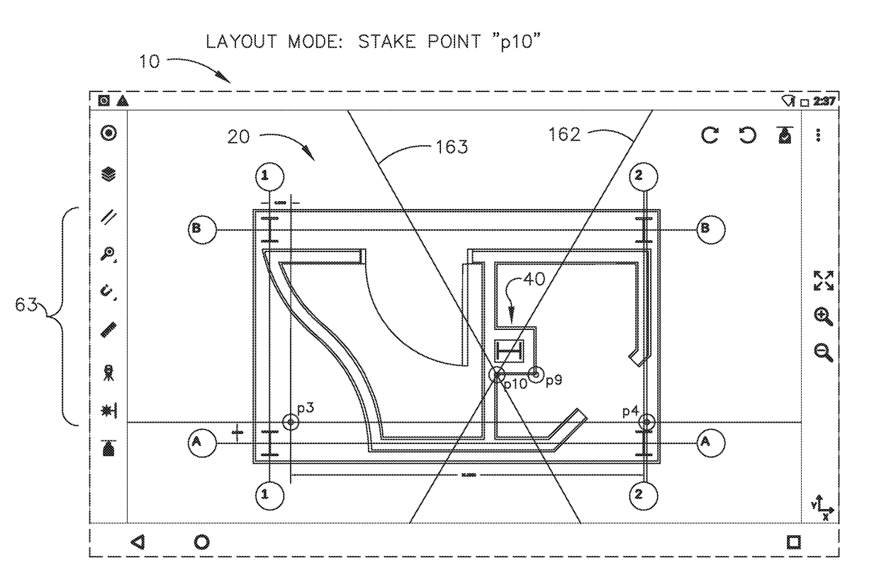
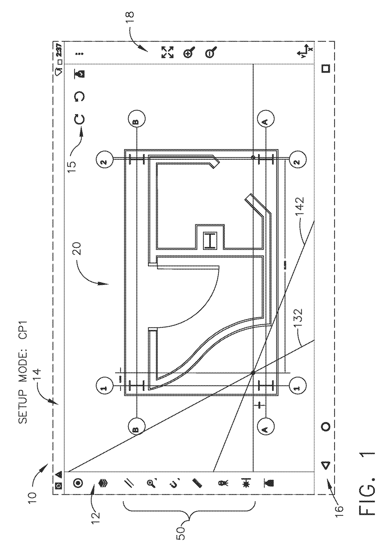
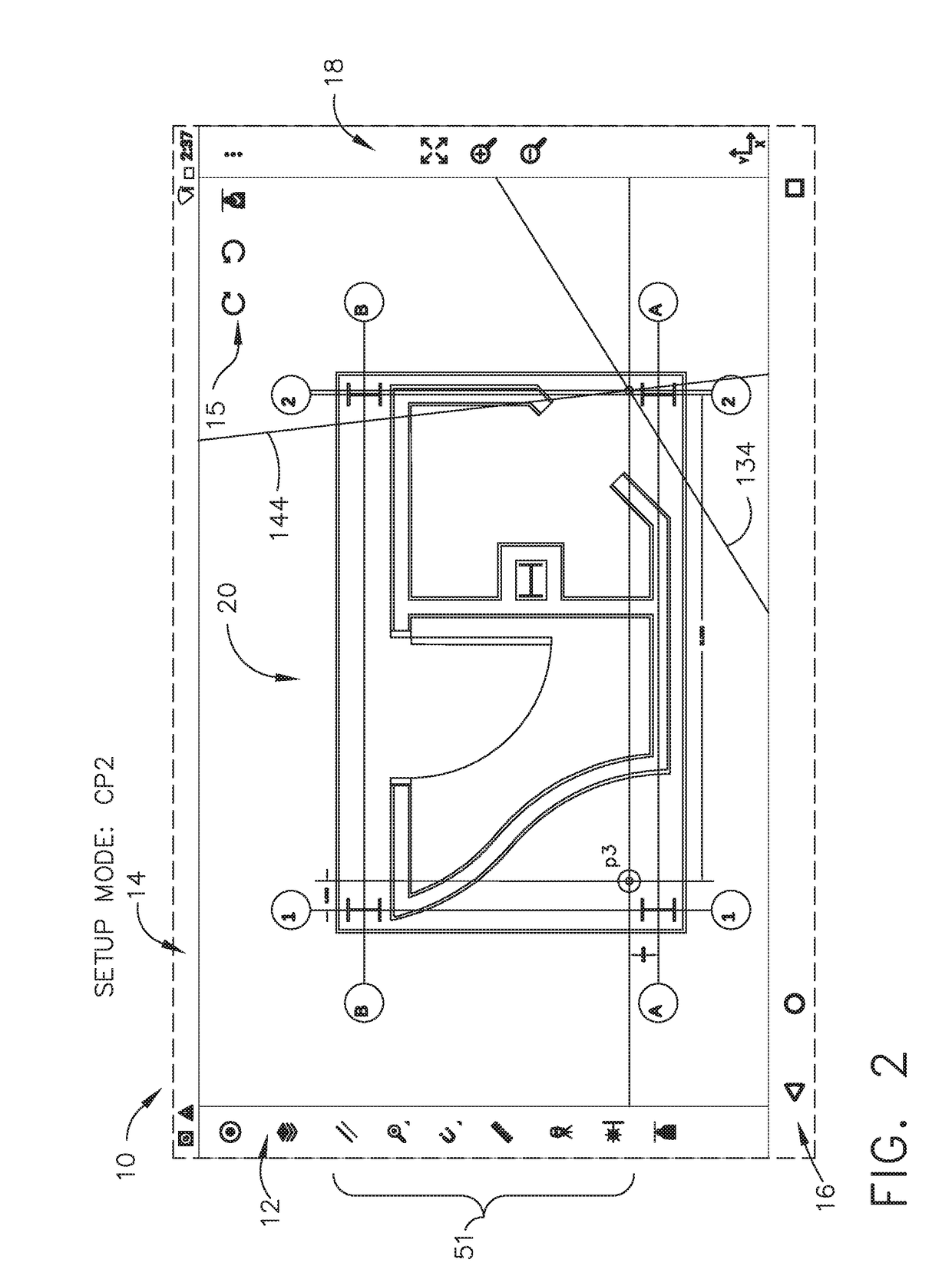
The remote controller in this patent allows users to display a virtual jobsite illustration as a CAD model and quickly create and stake points of interest in a single sequence of operations. Users can zoom in on a small portion of the jobsite floor and create points of interest while moving on to the next point of interest without changing modes of operation. Additionally, the patent describes an automatic point layout and staking system that utilizes laser controllers and a virtual jobsite illustration to direct a user's attention to specific points on the floor. Overall, this system improves efficiency and accuracy in the construction process.

Problems solved by technology

There may be some type of power on / off switch, but that would not necessarily be considered a true keypad (and typically would not be used for entering data).
Since it is difficult to work directly through a line that travels through uprights, the workers on the jobsite will typically offset a second chalk line by a certain distance, in which that offset chalk line is parallel to the original centerline between the I-beams.
Although most smart phones use touchscreen displays, not all portable (e.g., hand-held) computers use such touchscreen displays.

Method used


Image

  • Automatic point layout and staking system
  • Automatic point layout and staking system
  • Automatic point layout and staking system

Examples


Embodiment Construction

[0130]Reference will now be made in detail to the present preferred embodiment, an example of which is illustrated in the accompanying drawings, wherein like numerals indicate the same elements throughout the views.

[0131]It is to be understood that the technology disclosed herein is not limited in its application to the details of construction and the arrangement of components set forth in the following description or illustrated in the drawings. The technology disclosed herein is capable of other embodiments and of being practiced or of being carried out in various ways. Also, it is to be understood that the phraseology and terminology used herein is for the purpose of description and should not be regarded as limiting. The use of “including,”“comprising,” or “having” and variations thereof herein is meant to encompass the items listed thereafter and equivalents thereof as well as additional items. Unless limited otherwise, the terms “connected,”“coupled,” and “mounted,” and variat...


PUM


Abstract

An automatic point layout system identifies points and their coordinates using vertical planes of laser light. Laser controllers aim vertical laser light planes that will cross at any desired point on the jobsite floor. The user views a virtual jobsite illustration on a remote controller touchscreen display, and selects a point of interest. Commands are sent to the two laser controllers, which aim their laser transmitters at that point of interest, showing visible laser light lines that intersect directly at the point of interest, for staking. The user selects a second point of interest on the touchscreen display, commanding the laser transmitters to rotate to a new set of coordinates. The user performs these functions seamlessly; the remote controller allows the user to quickly move from one point of interest to the next, without having changing to any other operating mode between the identifying and staking of each new point.

Description

CROSS-REFERENCE TO RELATED APPLICATIONS[0001]None.TECHNICAL FIELD[0002]The technology disclosed herein relates generally to layout “surveying” equipment and is particularly directed to an automatic point layout and staking system of the type which identifies points and their coordinates, and transfers identified points on a physical jobsite surface using intersecting vertical planes of laser light. Embodiments are specifically disclosed using at least two laser controllers each having a laser light transmitter and certain laser light sensors, and with a remote controller that acts as a user interface with a touchscreen display, to control certain functions.[0003]When the system is set up, it is capable of aiming each of the vertical laser light planes that are output from the laser transmitters so that projected lines of laser light will cross on the surface at any desired point on the jobsite floor. The user can view a virtual jobsite illustration as a CAD model file on the remote ...

Claims


Application Information

Patent Timeline
Patent Type & Authority Applications(United States)
IPC IPC(8): G01C15/00G01S19/13G01B11/00G01S17/89G01S7/481
CPCG01C15/004G01S19/13G01B11/002A61B6/08G01S7/4813A61B6/587G01S17/89G01C15/002G01C15/02G01S1/70
Inventor TURNER, JAMIN MICHAELMORRISSEY, KEVIN MARCSNYDER, CHRIS WILLIAMHAJMOUSA, AYMAN ZUHDI
Owner SPECTRA PRECISION (USA) LLC
Learn More