Eureka AIR delivers breakthrough ideas for toughest innovation challenges, trusted by R&D personnel around the world.

Method and System for Hydraulic Communication with Target Well from Relief Well

a technology of target well and hydraulic communication, which is applied in the direction of fluid removal, directional drilling, borehole/well accessories, etc., can solve the problems of difficult to determine the distance and direction from the end of the relief well to the desired intersection point of the target well, and the difficulty of precision

Active Publication Date: 2018-11-08
HALLIBURTON ENERGY SERVICES INC
View PDF4 Cites 2 Cited by
  • Summary
  • Abstract
  • Description
  • Claims
  • Application Information

AI Technical Summary

Benefits of technology

The patent text describes a method for drilling a relief well to establish fluid communication with a target well without the need to intersect the two wells. This is achieved by positioning a portion of the relief well to be adjacent to the target well and then perforating in the radial direction of the target well. The method also involves using a latch mechanism and a non-rotational packer to facilitate the drilling process. The technical effect of this invention is to provide a safer and more efficient way to establish fluid communication between wells in hydrocarbon exploration.

Problems solved by technology

Since such ruptures, or blowouts, often produce extremely hazardous conditions at the surface in the vicinity of the original well, the relief well usually must be started a considerable distance away from the original wellhead.
Because the same problems of control of the direction of drilling that were encountered in the original well are also encountered in drilling the relief well, the location of the relief well borehole also cannot be known with precision; accordingly, it is extremely difficult to determine the distance and direction from the end of the relief well to the desired point of intersection on the target well.
In addition, the relief well usually is very complex, compounding the problem of knowing exactly where it is located with respect to a target that may be 10 inches in diameter at a distance of thousands of feet below the earth's surface.

Method used


Image

  • Method and System for Hydraulic Communication with Target Well from Relief Well
  • Method and System for Hydraulic Communication with Target Well from Relief Well
  • Method and System for Hydraulic Communication with Target Well from Relief Well

Examples


Embodiment Construction

[0014]The foregoing disclosure may repeat reference numerals and / or letters in the various examples. This repetition is for the purpose of simplicity and clarity and does not in itself dictate a relationship between the various embodiments and / or configurations discussed. Further, spatially relative terms, such as “beneath,”“below,”“lower,”“above,”“upper,”“uphole,”“downhole,”“upstream,”“downstream,” and the like, may be used herein for ease of description to describe one element or feature's relationship to another element(s) or feature(s) as illustrated in the figures. The spatially relative terms are intended to encompass different orientations of the apparatus in use or operation in addition to the orientation depicted in the figures. For example, if the apparatus in the figures is turned over, elements described as being “below” or “beneath” other elements or features would then be oriented “above” the other elements or features. Thus, the exemplary term “below” can encompass bo...


PUM


Abstract

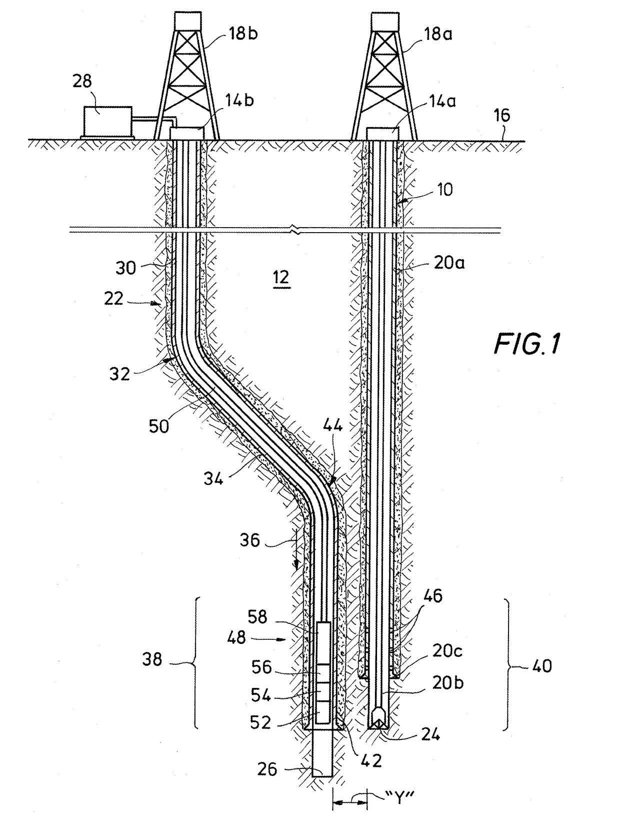
A system and method for establishing hydraulic communication between relief and target wells, wherein a relief well is drilled to include a portion of the target wellbore that is axially offset from and substantially parallel to a portion of the relief wellbore. A perforating system is carried by a tubing string in a cased portion of the relief well. The perforating system includes a latch assembly, a non-rotational packer and perforating gun having charges radially oriented in a limited direction. Tubing string parameters are obtained during the run-in of the perforating system, and thereafter the tubing string parameters are utilized to engage the latch assembly with a latch coupling carried by the casing in the relief wellbore. Axial and rotational forces are applied to the tubing string to engage the latch assembly. Discharge of the perforating gun yields perforations only between the relief well and target well, establishing fluid communication.

Description

BACKGROUNDTechnical Field[0001]Embodiments disclosed herein relate to well intervention operations in hydrocarbon exploration. In particular, embodiments disclosed herein relate to the development of hydraulic communication between a target and a relief well without the need to intersect the two wells.Description of Related Art[0002]In the field of hydrocarbon exploration and extraction, it is sometimes necessary to establish fluid communication between two wells.[0003]One example occurs in the situation where it becomes necessary to drill a relief well to intersect an existing well, as in the case where the casing of the existing well has ruptured and it becomes necessary to plug the existing well at or below the point of the rupture to bring it under control. In order to do this, the relief well must be drilled to intersect the original well at the desired level, thus establishing fluid communication between the two wells. The relief well provides a conduit for injecting a fluid, ...

Claims


Application Information

Patent Timeline
IPC IPC(8): E21B43/117E21B43/119E21B43/12E21B43/30E21B7/04E21B33/129E21B33/128
CPCE21B43/117E21B43/119E21B43/12E21B43/305E21B7/04E21B33/1292E21B33/128E21B43/30
Inventor HESS, JOE E.CUTHBERT, ANDY J.CRAMM, CARL J.
Owner HALLIBURTON ENERGY SERVICES INC
Why Eureka
Eureka Blog
Learn More