Solar Shading Module, Glazed Structure, Building, And Method Of Operating A Solar Shading Module

Active Publication Date: 2018-11-08
SOLARSWING ENERGY BV
View PDF1 Cites 3 Cited by
  • Summary
  • Abstract
  • Description
  • Claims
  • Application Information

AI Technical Summary

Benefits of technology

The invention aims to provide maximum shading while using thin shading panels that are smaller than the width and length of the panel. This allows the panels to be positioned close to each other without interfering with the movement of the solar tracking system. Additionally, measures can be taken to prevent direct sunlight from passing between adjacent modules, such as positioning them close to each other or adding shielding members.

Problems solved by technology

However, a drawback of the vertical and horizontal blinds when for instance used in a façade of a building is that the blinds obstruct the view of an observer in many directions, i.e. the unobstructed view factor is relatively low.
Although the provision of a solar tracking system has led to improvement, the improvement is not sufficient.
However, so far, it has been found difficult to improve the unobstructed view factor while at the same time blocking all direct sunlight in substantially all possible positions of the sun.
However, the unobstructed view factor is still relatively low.

Method used


Image

  • Solar Shading Module, Glazed Structure, Building, And Method Of Operating A Solar Shading Module
  • Solar Shading Module, Glazed Structure, Building, And Method Of Operating A Solar Shading Module
  • Solar Shading Module, Glazed Structure, Building, And Method Of Operating A Solar Shading Module

Examples


Embodiment Construction

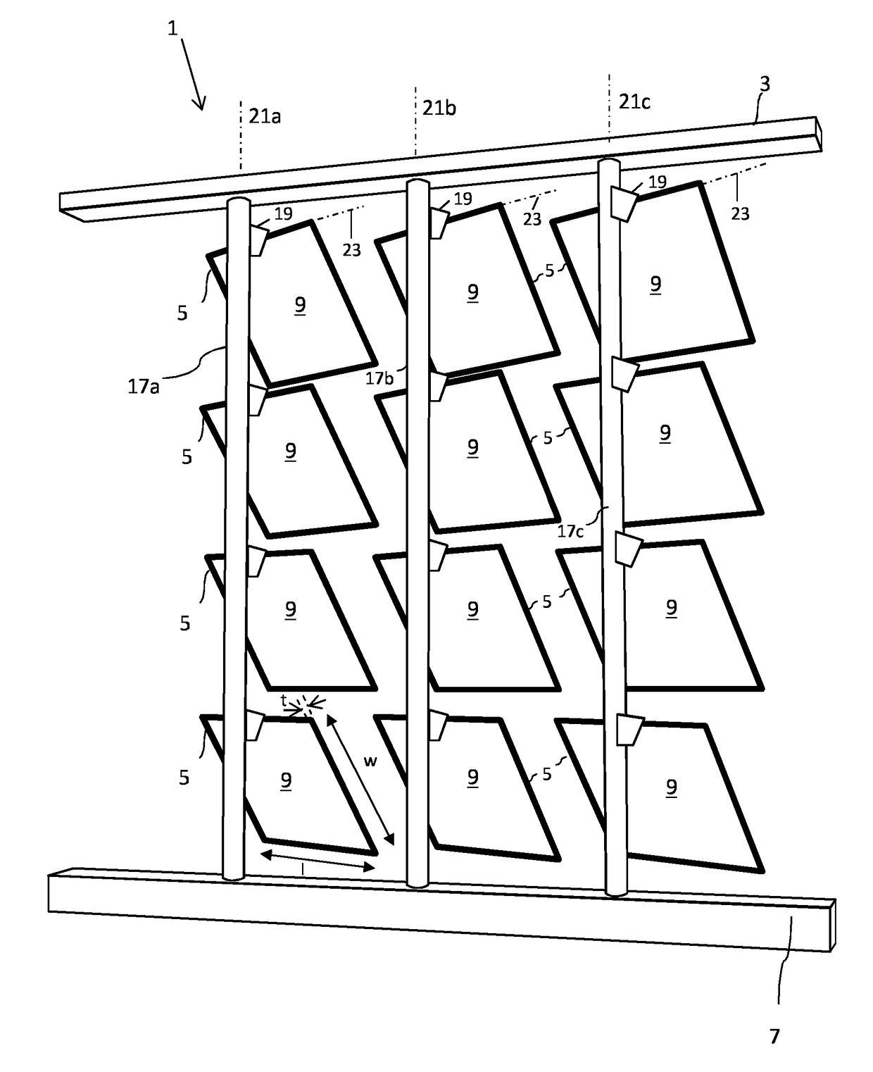
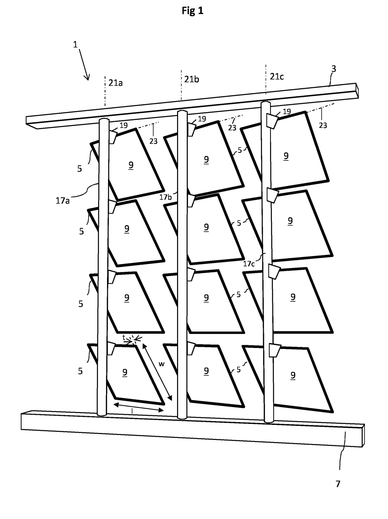
[0060]FIGS. 1, 2 and 3A to 3C depict schematically a solar shading module 1 for shading direct sunlight, said module 1 comprising a frame 3, and array of 3 by 4 shading panels 5, and a solar tracking system 7 configured to move the shading panels 5 in order to follow the sun.

[0061]FIG. 1 depicts the module 1 seen from a shaded side of the module 1, while FIG. 2 depicts the module 1 seen from a sun side of the module 1. FIG. 3A depicts a top view, FIG. 3B a front view, and FIG. 3C a side view. In FIGS. 3A, 3B and 3C the shading panels have all been positioned in a single plane in front of the frame 3. In FIGS. 1 and 2, the shading panels have all been rotated similarly.

[0062]The array of 3 by 4 shading panels is a mere example. The smallest array falling within the terms of the invention is an array of 2 by 2 shading panels, but the array may also be much larger. For simplicity reasons, the example is chosen to be relatively small. Hence, every practical m×n array can be envisaged wi...


PUM


Abstract

This invention relates to a solar shading module (1) for shading direct sunlight, wherein maximum shading is combined with a high unobstructed view factor by providing an array of m×n shading panels (5) which are moved by a solar tracking system (7) in order to follow the sun. The invention further relates to a glazed structure and a building provided with one or more solar shading modules (1) according to the invention, for instance as part of a fagade or roof of the building. The invention also relates to a method for operating a solar shading module (1) according to the invention, comprising the step of controlling the position of the shading panels (5) such that the normal of the shading panels (5) points towards the sun.

Description

BACKGROUND OF THE INVENTION[0001]The invention relates to a solar shading module for shading direct sunlight, and to a glazed structure, such as a façade, roof, and sound barrier along a highway, comprising one or more solar shading modules. The invention further relates to a building comprising one or more solar shading modules. The invention also relates to a method for operating a solar shading module according to the invention.[0002]Well-known shading modules usually comprise vertical or horizontal blinds that can be rotated about their longitudinal axis allowing the blinds to be positioned such that preferably all direct sunlight is blocked by the blinds.[0003]However, a drawback of the vertical and horizontal blinds when for instance used in a façade of a building is that the blinds obstruct the view of an observer in many directions, i.e. the unobstructed view factor is relatively low. In other words, the blinds also block much of the indirect light.[0004]To improve the unobs...

Claims


Application Information

Patent Timeline
IPC IPC(8): E04F10/10E06B7/086F24S20/66F24S20/67F24S30/45H02S20/21H02S20/22H02S20/32
CPCE04F10/10E06B7/086F24S20/66F24S20/67F24S30/45H02S20/21H02S20/22H02S20/32F24S2020/183Y02B10/20H02S20/10F24S50/20E06B9/24Y02E10/47Y02E10/44Y02B10/10
Inventor DE RIDDER, CHRISTIAAN MARTINUS PETRUSKIN, SAMKOUTERS, LUCAS JOHANNES CORNELISKNEPPERS, JOB LEONARDUS
Owner SOLARSWING ENERGY BV
Why Eureka
Try Eureka