
Zoom lens and imaging apparatus

a zoom lens and imaging apparatus technology, applied in the field of zoom lenses, can solve the problems of inability to achieve the reduction of size, increase in the size of the first lens group, and large number of lenses of the first lens group, and achieve the effects of high optical performance, small size, and high zoom ratio

Active Publication Date: 2018-10-18
FUJIFILM CORP
View PDF0 Cites 1 Cited by
  • Summary
  • Abstract
  • Description
  • Claims
  • Application Information

AI Technical Summary

Benefits of technology

The present invention provides a zoom lens that can be configured to have a small size while ensuring a high zoom ratio and has high optical performance by satisfactorily correcting chromatic aberration. The zoom lens includes a first lens group that has a positive refractive power and remains stationary during zooming, a plurality of movable lens groups that move during zooming, and a final lens group that has a positive refractive power and remains stationary during zooming. The configuration of the first lens group is appropriately set, and one or more movable lens groups are set as negative lens groups. This configuration allows for a compact size, high zoom ratio, and performance, while also satisfactorily correcting chromatic aberration. The imaging apparatus, which uses this zoom lens, achieves high-quality images with a smaller size and greater zoom range.

Problems solved by technology

However, in a case where the configuration is intended to be applied, the number of lenses of the first lens group tends to be large, and this leads to an increase in size of the first lens group.
However, in the lens system described in JP2015-94866A, the number of lenses of the first lens group is large and reduction in size is not achieved, or the zoom ratio is insufficient.
Therefore, in this lens system, there is a disadvantage that the axial marginal ray should be shielded by using a member other than the aperture stop in a part of the zoom range so as not to cause large longitudinal chromatic aberration.

Method used


Image

  • Zoom lens and imaging apparatus
  • Zoom lens and imaging apparatus
  • Zoom lens and imaging apparatus

Examples


example 1

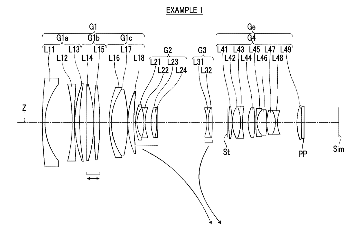
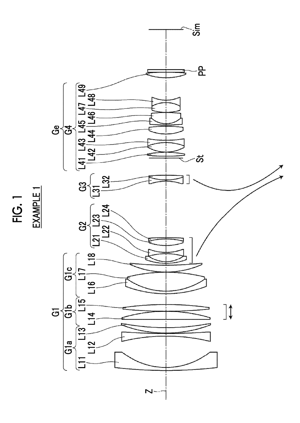
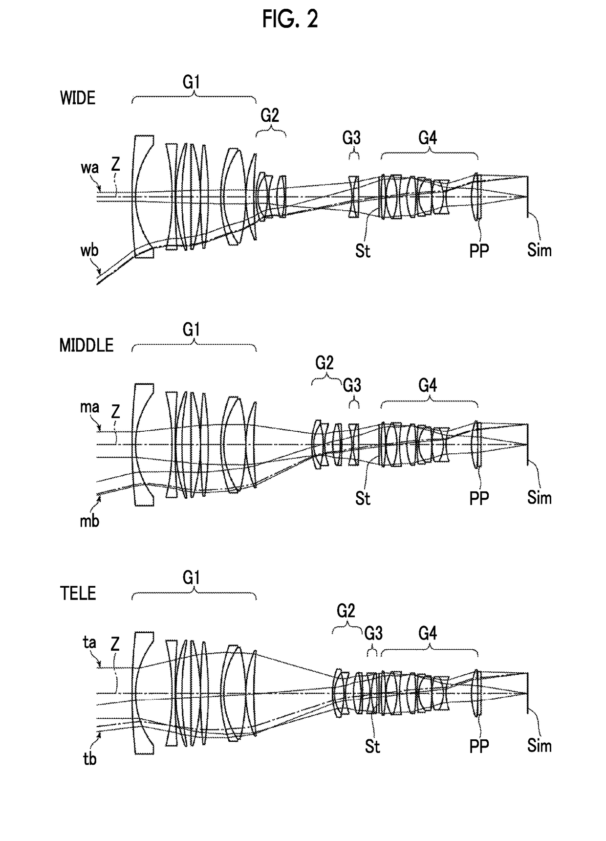
[0089]A lens configuration of a zoom lens of Example 1 is shown in FIGS. 1 and 2, and an illustration method thereof is as described above. Therefore, repeated description is partially omitted herein. The zoom lens of Example 1 consists of, in order from the object side, a first lens group G1, a second lens group G2, a third lens group G3, an aperture stop St, and a fourth lens group G4. In these four lens groups, the distances in the direction of the optical axis between groups adjacent to each other change during zooming. Both the second lens group G2 and the third lens group G3 are movable lens groups having negative refractive powers. The first lens group G1 consists of, in order from the object side, a first lens group front group G1a that consists of three lenses and has a negative refractive power, a first lens group intermediate group G1b that consists of two lenses and has a positive refractive power, and a first lens group rear group G1c that consists of three lenses and h...

example 2

[0101]FIG. 4 is a cross-sectional view of a zoom lens of Example 2. The zoom lens of Example 2 consists of, in order from the object side, a first lens group G1, a second lens group G2, a third lens group G3, an aperture stop St, and a fourth lens group G4. The first lens group G1 consists of, in order from the object side, a first lens group front group G1a consisting of three lenses, a first lens group intermediate group G1b consisting of two lenses, and a first lens group rear group G1c consisting of three lenses. The present example is the same as Example 1 in terms of the signs of refractive powers of the lens groups, the lens groups moving during zooming, and the lens groups moving during focusing.

[0102]Table 4 shows basic lens data of the zoom lens of Example 2, Table 5 shows values of specification and variable surface distances, Table 6 shows aspheric coefficients, and FIG. 9 shows aberration diagrams in a state where the object at infinity is in focus.

TABLE 4Example 2SiRiD...

example 3

[0103]FIG. 5 is a cross-sectional view of a zoom lens of Example 3. The zoom lens of Example 3 consists of, in order from the object side, a first lens group G1, a second lens group G2, a third lens group G3, a fourth lens group G4, an aperture stop St, and a fifth lens group G5. In these five lens groups, the distances in the direction of the optical axis between groups adjacent to each other change during zooming. The second lens group G2 has a positive refractive power, the third lens group G3 has a negative refractive power, and the fourth lens group G4 has a negative refractive power. The three lens groups including the second to fourth lens groups G2 to G4 are respectively movable lens groups. The first lens group G1 consists of, in order from the object side, a first lens group front group G1a consisting of three lenses, a first lens group intermediate group G1b consisting of two lenses, and a first lens group rear group G1c consisting of three lenses. The signs of the refrac...


PUM


Abstract

The zoom lens consists of, in order from the object side, a first lens group that has a positive refractive power and remains stationary during zooming, a plurality of movable lens groups that move during zooming, and a final lens group that has a positive refractive power and remains stationary during zooming. The first lens group consists of, in order from the object side, a first lens group front group that has a negative refractive power, a first lens group intermediate group that has a positive refractive power and moves during focusing, and a first lens group rear group that has a positive refractive power. The first lens group front group has, successively in order from a position closest to the object side, a negative meniscus lens concave toward an image side, and a negative lens concave toward the object side. The components of the zoom lens satisfy predetermined conditional expressions.

Description

CROSS-REFERENCE TO RELATED APPLICATIONS[0001]This application is a Continuation of PCT International Application No. PCT / JP2016 / 080923 filed on Oct. 19, 2016, which claims priority under 35 U.S.C. § 119(a) to Japanese Patent Application No. 2016-013135 filed on Jan. 27, 2016. Each of the above application(s) is hereby expressly incorporated by reference, in its entirety, into the present application.BACKGROUND OF THE INVENTION1. Field of the Invention[0002]The present invention relates to a zoom lens suitable for movie imaging cameras, broadcast cameras, digital cameras, video cameras, and surveillance cameras, and to an imaging apparatus comprising the zoom lens.2. Description of the Related Art[0003]In the related art, a zoom lens having a four-group configuration or a five-group configuration has been proposed as a lens system that can be used for cameras in the above-mentioned fields. For movie imaging cameras and broadcast cameras, the change in the total length of the lens sys...

Claims


Application Information

Patent Timeline
IPC IPC(8): G02B15/167G02B13/18G02B13/02
CPCG02B15/167G02B13/18G02B13/02G02B15/144109G02B15/145119G02B15/145121G02B3/04G02B5/005G02B9/34G02B9/60G02B9/62G02B9/64G02B13/0015G02B13/0045G02B13/009G02B15/14
Inventor YONEZAWA, MASARUIKEDA, SHINKICHI
Owner FUJIFILM CORP
Learn More