
Curvature-adjustable backboard assembly and curved display device

a backboard and display module technology, applied in the field of display technology, can solve the problems of irregular display device, poor display capability of the edge of the screen, backboards formed with these two measures do not allow for the curvature adjustment of the curved display module, etc., to achieve the effect of low-speed position-limiting electric machine, continuous adjustment, and easy and efficient adjustmen

Active Publication Date: 2018-10-18
SHENZHEN CHINA STAR OPTOELECTRONICS TECH CO LTD
View PDF24 Cites 3 Cited by
  • Summary
  • Abstract
  • Description
  • Claims
  • Application Information

AI Technical Summary

Benefits of technology

The present invention provides a backboard assembly that can adjust its curvature easily and efficiently, and a curved display device that uses this assembly. This allows users to acquire different displaying conditions while viewing the display, improving its attraction to the market and making the structure simple and easy to achieve.

Problems solved by technology

Generally speaking, the curved display device allows for the best viewing effect from center to edge, while a regular display device has poor capability of displaying at edges of a screen.
The backboards formed with these two measures do not allow for adjustability of the curvature of the curved display modules.
In other words, the curvature of a curved display device is fixed and no adjustability of curvature can be made for one curved display device to suit the needs for different applications and it is not possible to do any adjustability to suit the needs of user's observation.
Image displaying can be available for one single, fixed curvature and thus, the view angle is limited.

Method used


Image

  • Curvature-adjustable backboard assembly and curved display device
  • Curvature-adjustable backboard assembly and curved display device
  • Curvature-adjustable backboard assembly and curved display device

Examples


Embodiment Construction

[0040]To further expound the technical solution adopted in the present invention and the advantages thereof, a detailed description will be given with reference to the preferred embodiments of the present invention and the drawings thereof

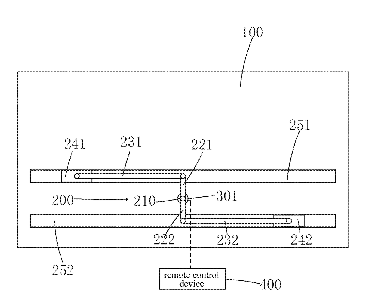
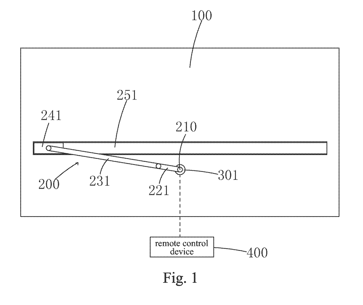
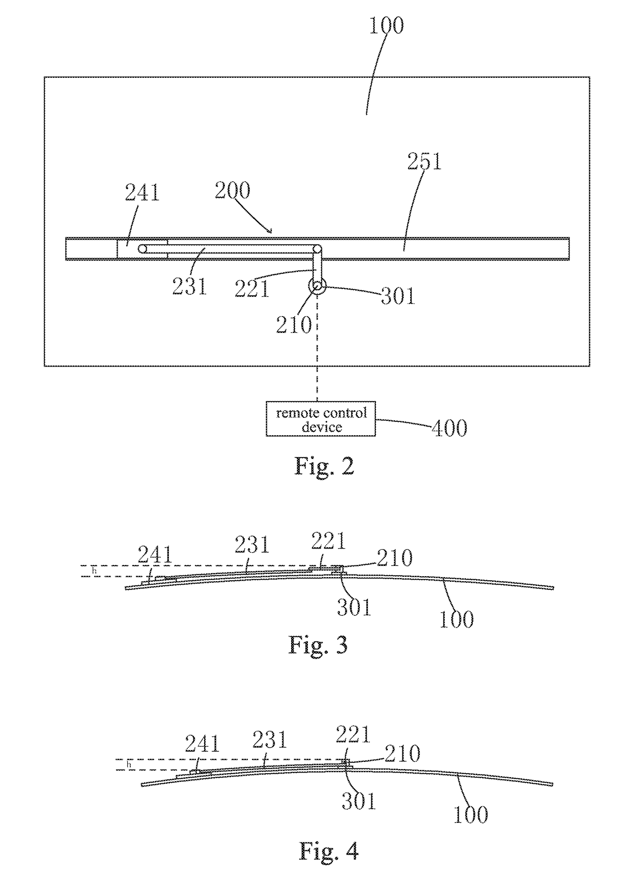
[0041]Referring to FIGS. 1-2, FIGS. 1 and 2 are schematic rear views respectively illustrating a curvature-adjustable backboard assembly according to a first embodiment of the present invention in a state of maximum radius of curvature and a state of minimum radius of curvature. In the instant embodiment, the curvature-adjustable backboard assembly comprises a backboard 100 that is curvable, a slider-crank mechanism 200, and a first low-speed position-limiting electric machine 301.

[0042]The slider-crank mechanism 200 comprises a central pivot 210, a first crank 221, a first connection rod 231, a first slider 241, and the first rail 251, wherein the central pivot 210 and the first rail 251 are fixed on the backboard 100; the first slider 241 is moun...


PUM


Abstract

The present invention provides a curvature-adjustable backboard assembly and a curved display device. The curvature-adjustable backboard assembly of the present invention includes a curvable backboard, a slider-crank mechanism, and a first low-speed position-limiting electric machine. The slider-crank mechanism comprises a central pivot and a first rail that are fixed to the backboard, a first slider mounted to the first rail, a first crank that is rotatable about the central pivot as being driven by the first low-speed position-limiting electric machine, and a first connection rod having two ends respectively and pivotally coupled to the first slider and the first crank, wherein when the first crank is driven to rotate, the first connection rod drives the first slider to move along the first rail and during the movement of the first slider along the first rail, a height of an arched form of the backboard with respect to the central pivot at a location where the first slider passes may vary accordingly so as to allow for easy and efficient variation of a curvature of the backboard according to a desired curving condition.

Description

BACKGROUND OF THE INVENTION1. Field of the Invention[0001]The present invention relates to the field of display technology, and more particular to a curved backboard assembly and a curved display device.2. The Related Arts[0002]Recently, with the development of display technology, major manufacturers have marketed curved display devices, such as curved television. Generally speaking, the curved display device allows for the best viewing effect from center to edge, while a regular display device has poor capability of displaying at edges of a screen. The curved display device has a screen that is entirely of a curved design to provide a wide full-view image, providing the same visual enjoyment at both the central portion and the circumferential portion of the screen, ensuring clarity of observation of image at two opposite side edges of the screen, and also reducing distortion of off-axis viewing for viewing at a short distance, making the entire screen spacing from human eye lens by...

Claims


Application Information

Patent Timeline
IPC IPC(8): F16H21/22H05K5/00H05K5/02
CPCF16H21/22H05K5/0017H05K5/0217G09F9/301F16H21/24F16H21/34G02F1/1333
Inventor CHEN, WEIFENG
Owner SHENZHEN CHINA STAR OPTOELECTRONICS TECH CO LTD
Learn More