Peristaltic Pump

a pump and peristaltic technology, applied in the direction of positive displacement liquid engines, shafts, bearings, etc., can solve the problems of time-consuming and thus costly processes, and the cost of coupling itsel

Active Publication Date: 2018-09-20
WATSON MARLOW BREDEL
View PDF3 Cites 1 Cited by
  • Summary
  • Abstract
  • Description
  • Claims
  • Application Information

AI Technical Summary

Benefits of technology

[0007]It is therefore desired to provide a pump which addresses the issues of conventional direct-drive pumps and provides greater tolerance of misalignments.

Problems solved by technology

However, this process is time consuming and thus costly.
The coupling itself is also expensive.
However, with such a design, the drive unit itself must handle the large force exerted on the rotor while compressing the tube.
However, with such a direct-coupled pump, the orientation of the rotor is fixed with respect to the hub which does not allow for any angular misalignment between the components which may result from manufacturing tolerances.

Method used


Image

  • Peristaltic Pump
  • Peristaltic Pump
  • Peristaltic Pump

Examples


Embodiment Construction

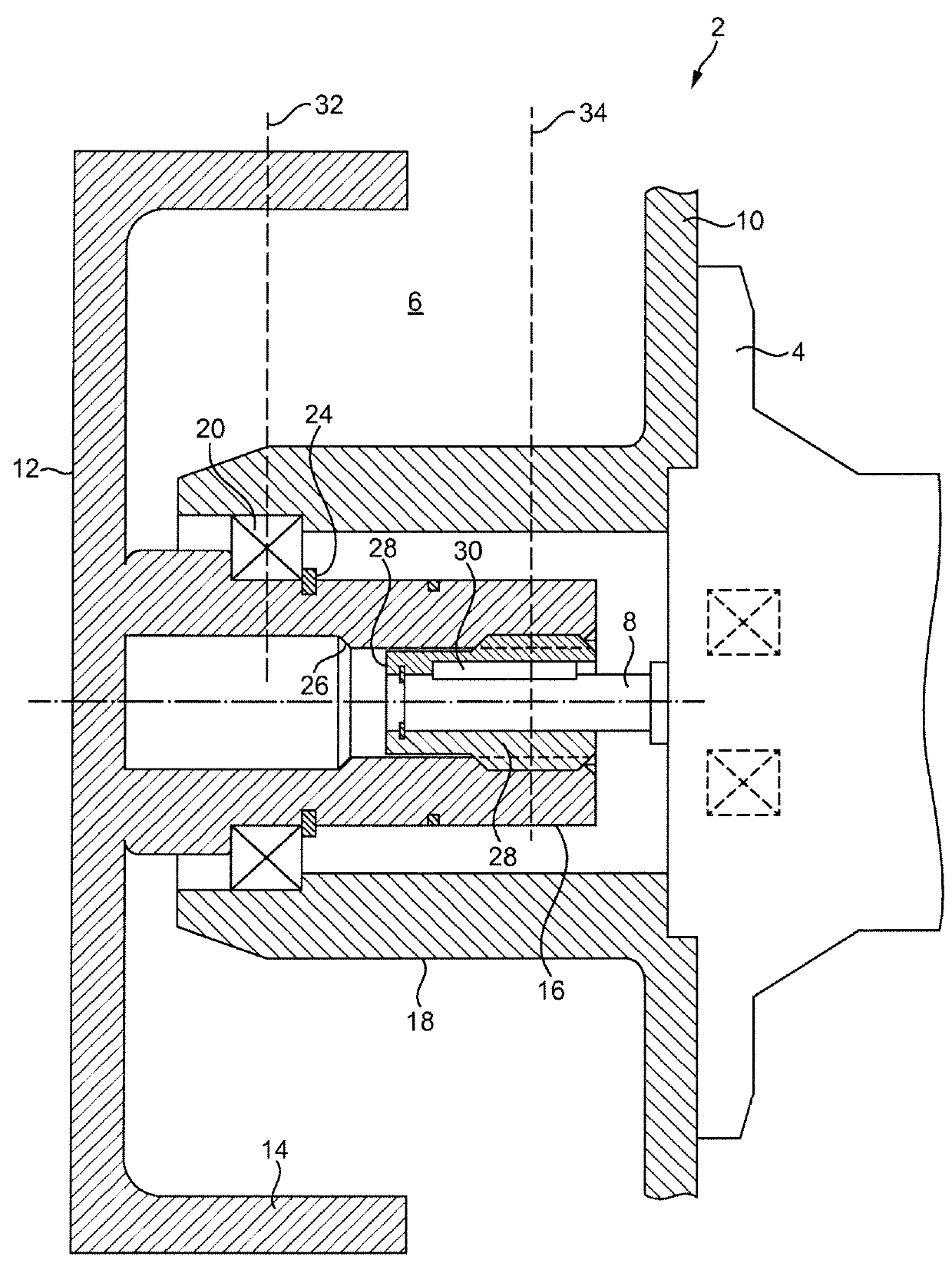
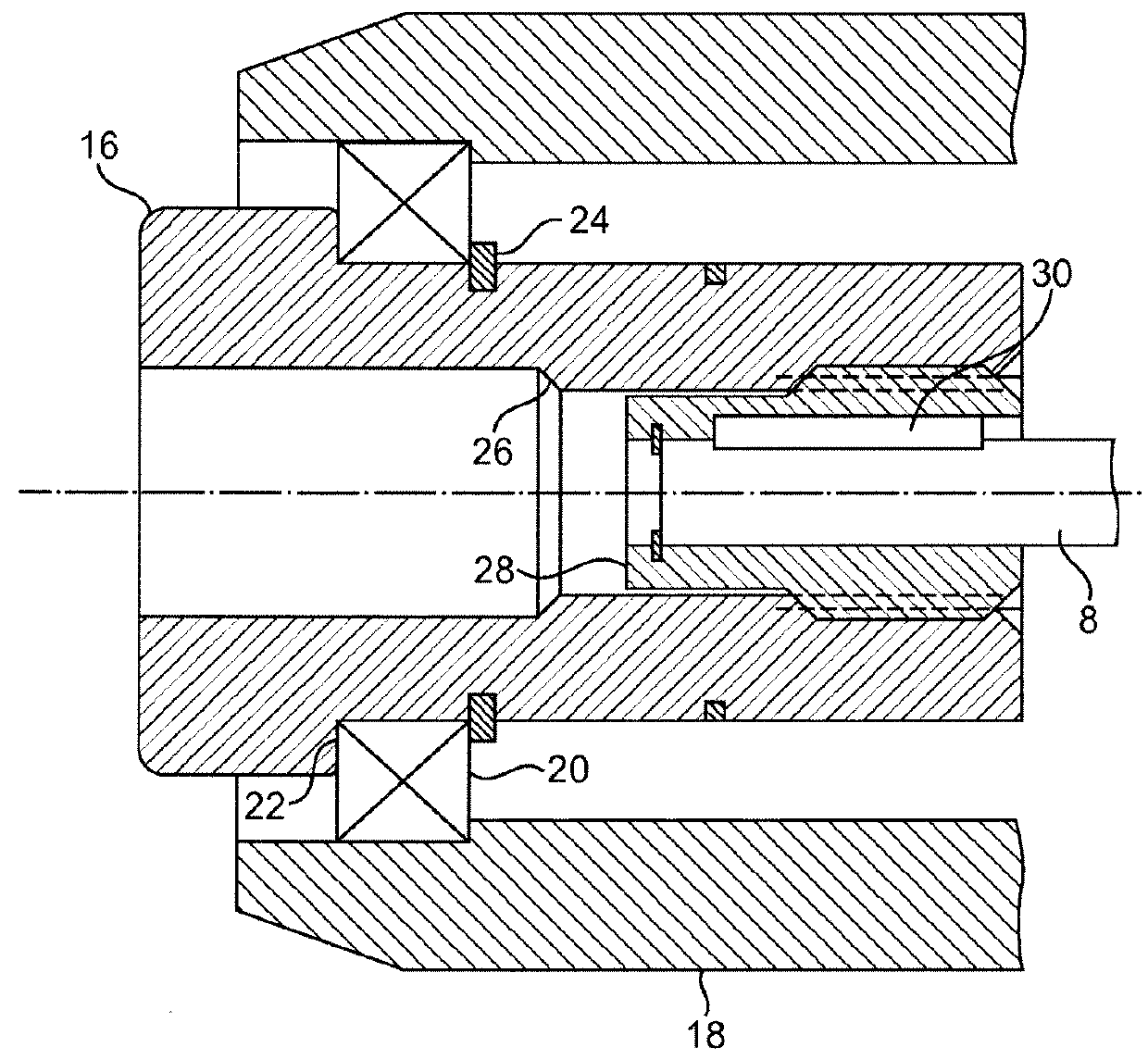
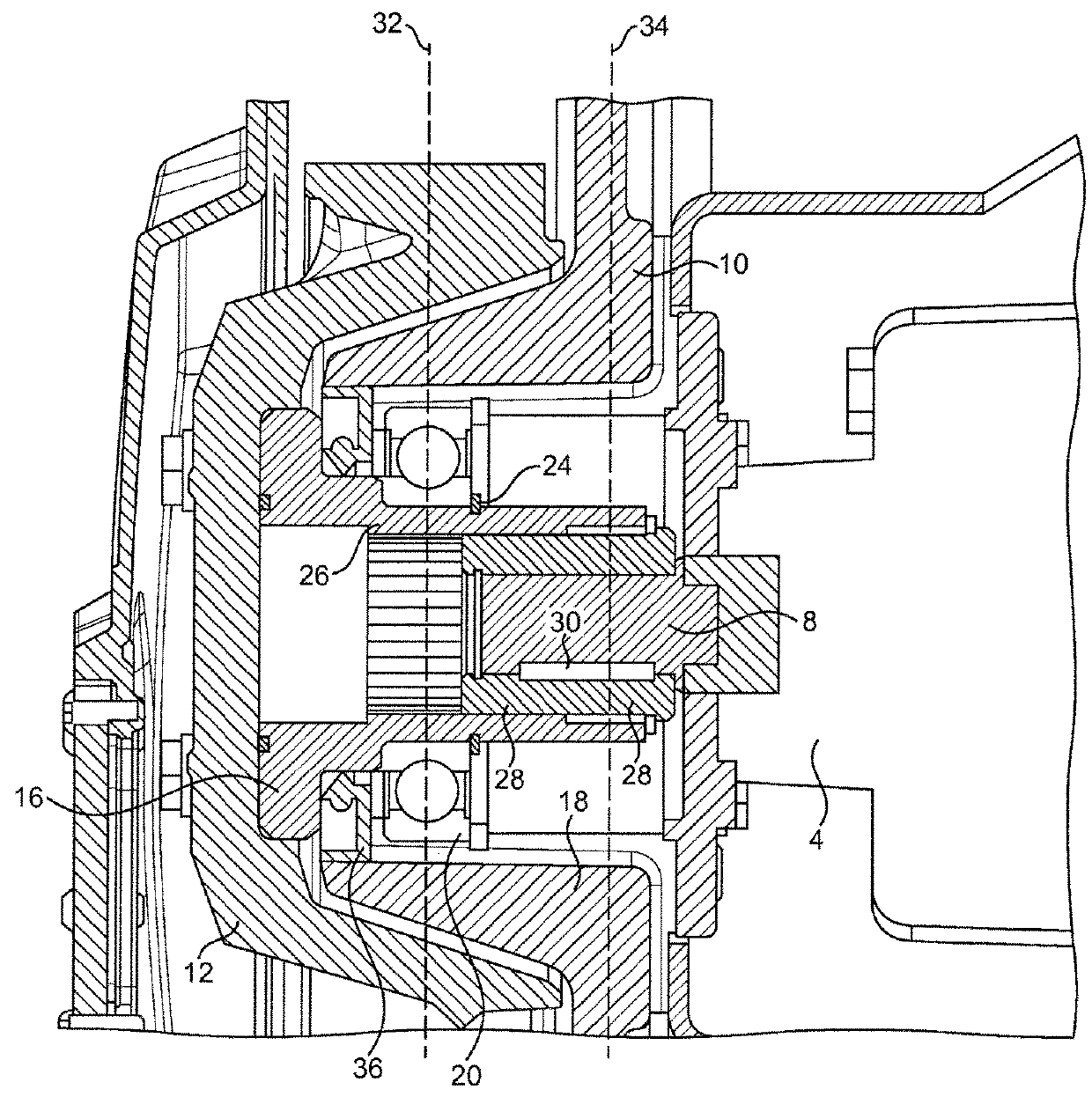
[0024]FIGS. 1 and 2 show a peristaltic pump 2 according to an embodiment of the invention. The peristaltic pump 2 comprises a drive unit 4 and a pumphead 6. The drive unit 4 comprises a motor which provides drive via an output shaft 8 of a gearbox, such as a helical gearbox.

[0025]The pumphead 6 comprises a housing 10 which is affixed to the drive unit 4. A rotor 12 is disposed within the housing 10. The rotor 12 comprises an outer rim 14 having a pair of shoes (not shown) for engagement with a flexible tube or hose (not shown) disposed between the outer rim 14 of the rotor 12 and an outer wall (not shown) of the housing 10. As the rotor 12 rotates, the shoes deform the flexible tube to form an occlusion in the tube. As the occlusion moves along the length of the tube, fluid in the tube is forced from one end to the other. A lubricating fluid may be provided within the housing to reduce friction between the shoes and the tube and thus to reduce wear. Accordingly, the housing 10 may f...


PUM


Abstract

A peristaltic pump comprising: a housing having a hub; a rotor disposed within the housing and rotatably supported by the hub, the rotor comprising a drive shaft which extends through the hub, the drive shaft configured to engage with an output shaft of a drive unit to form a drive connection; wherein a first misalignment pivot is formed between the rotor and the hub and a second misalignment pivot is formed between the drive shaft and the output shaft of the drive unit.

Description

BACKGROUND[0001]The invention relates to a peristaltic pump.[0002]Peristaltic pumps generally comprise a drive motor connected via a gearbox to drive a rotor housed in a pumphead. The rotor carries a pair of shoes or other means for engagement with a flexible tube. As the rotor rotates, the shoes deform the flexible tube to form an occlusion in the tube. As the occlusion moves along the length of the tube, fluid in the tube is forced from one end to the other.[0003]Conventional pumps can generally be classified as either long-coupled or close-coupled pumps.[0004]In a long-coupled pump, the drive unit is coupled to the pumphead via a coupling. Any misalignment (both angle and position) between the drive unit and the pumphead can be corrected via the coupling. However, this process is time consuming and thus costly. The coupling itself is also expensive.[0005]With close-coupled pumps, the rotor is connected directly to the drive unit thereby eliminating the need for a coupling and the...

Claims


Application Information

Patent Timeline
Patent Type & Authority Applications(United States)
IPC IPC(8): F04B43/12F16C19/06
CPCF04B43/1261F16C19/06F16C2360/00F04B43/12F04B45/08
Inventor OUDE VRIELINK, RONALDVAN DER SPAN, FOKKE PATRICKLITTOOIJ, JONATHAN ADRIANUS
Owner WATSON MARLOW BREDEL
Why Eureka
Try Eureka