
Conveyor support rail attachment, support rail and conveyor

a technology of conveyors and support rails, applied in conveyors, packaging, transportation and packaging, etc., can solve the problems of parts that must be kept, dusty, wet and/or messy environment, and take a lot of time, effort and manpower, so as to reduce the wear of conveyor chains and facilitate removal and remounting

Active Publication Date: 2018-09-13
FLEXLINK
View PDF2 Cites 1 Cited by
  • Summary
  • Abstract
  • Description
  • Claims
  • Application Information

AI Technical Summary

Benefits of technology

This patent is for an improved conveyor support rail attachment that makes it easier to clean the conveyor. The attachment allows for cleaning the support rail without removing it, which is done by using a rounded attachment means that minimizes contact points. The support rail can be flexed slightly in a sideway direction, creating a small gap between the attachment means and the support rail, which makes it easy to clean. The attachment is easily mounted and removed, and the support rail can be easily removed and remounted from above. The attachment means securely hold the support rail in place, and the support rail can be symmetrical or have a side support. This makes it easy to clean the conveyor system without removing its support rails.

Problems solved by technology

For some products, such as medical equipments or in lab automation, the environment is clean and dust free, whereas for other products, the environment may be dusty, wet and / or messy.
While this solution makes the conveyor system easier to clean, it requires partial disassembly of the conveyor system, which takes a lot of time, effort and manpower.
Another problem with the removal of parts is that the parts must be kept somewhere during the cleaning.
There is also a risk that fasteners or other parts are lost and not replaced, which may lead to malfunction of the conveyor system.
This solution allows guide rails that are worn to be replaced, but is not suitable for daily removal in order to clean the parts of the conveyor.

Method used


Image

  • Conveyor support rail attachment, support rail and conveyor
  • Conveyor support rail attachment, support rail and conveyor
  • Conveyor support rail attachment, support rail and conveyor

Examples


Embodiment Construction

[0028]The embodiments of the invention with further developments described in the following are to be regarded only as examples and are in no way to limit the scope of the protection provided by the patent claims. References such as longitudinal, horizontal, vertical, right, left etc. refer to directions of a conveyor in normal use.

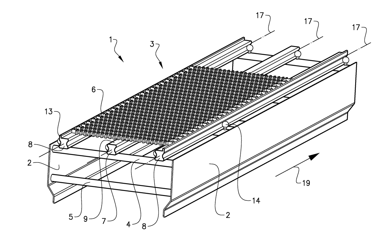
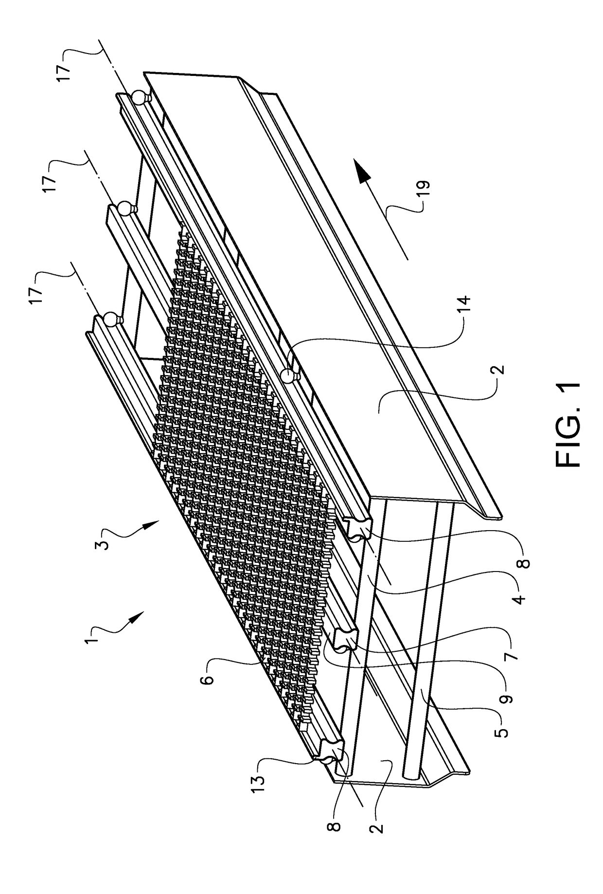
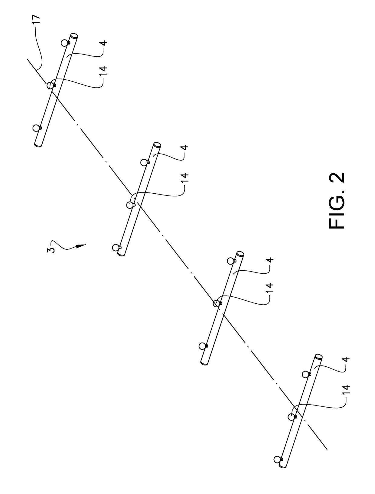
[0029]FIG. 1 shows a view of a conveyor comprising a conveyor support rail attachment according to the invention. FIG. 2 shows the conveyor support rail attachment, FIG. 3a shows the conveyor support rail attachment with a support rail in a vertical cut view, and FIG. 4a shows another example of a conveyor support rail attachment with a support rail in a vertical cut view. The conveyor 1 comprises two side walls 2. The side walls acts in this example both as longitudinal beams which hold the conveyor together and as protective covers which helps to prevent fingers and other objects to get caught in the conveyor chain. The conveyor further comprises a plur...


PUM


Abstract

Conveyor support rail attachment, comprising a plurality of attachment means arranged spaced apart along a longitudinal centre axis, where every second attachment means is arranged on a leftside of the centre axis and every other attachment means is arranged on a right side of the centre axis, and where each attachment means is provided with a bearing surface adapted to bear against a side section of a support rail, such that the support rail is supported only on one side at each attachment means. The advantage of the invention is that a support rail can easily be mounted to and removed from the conveyor support rail attachment, and further that the bearing surface between the support rail and the attachment means can be minimized. This allows for a support rail that is easy to clean.

Description

TECHNICAL FIELD[0001]The present invention relates to an attachment for a support rail adapted to be used in conveyor systems, both for easy to clean conveyors and for ordinary conveyor systems. The attachment for a support rail is adapted to simplify the cleaning of the conveyor system.BACKGROUND ART[0002]Conveying devices, such as those which are used for moving objects between different stations in a factory, usually comprise a conveying track comprising a belt or a chain. A conveyor track consists of an endless conveyor chain or belt that is supported by conveyor beams. The conveyor chain or belt glides on sliding surfaces on the conveyor beams in order to reduce the friction and the wear. This surface may be the conveyor beam itself or may be an additional component, such as a slide rail. The conveyor track may comprise curves and bends and at the end regions of a conveyor track, there is either a drive unit which drives the chain or an idler end unit which supports the chain f...

Claims


Application Information

Patent Timeline
Patent Type & Authority Applications(United States)
IPC IPC(8): B65G21/22
CPCB65G21/22B65G2207/26B65G15/62B65G21/06
Inventor ASKERDAL, MAGNUSSNABB, JOSEF
Owner FLEXLINK
Learn More