Step-scanning sensing beam for imaging interferometer

a technology of imaging interferometer and sensing beam, which is applied in the direction of measuring devices, instruments, using optical means, etc., can solve the problems of challenging to support a large beam moving range, and to use a mechanical beam scanning device such as a scanning mirror

Inactive Publication Date: 2018-08-23
WAN XIAOKE
View PDF0 Cites 12 Cited by
  • Summary
  • Abstract
  • Description
  • Claims
  • Application Information

AI Technical Summary

Benefits of technology

[0009]One embodiment describes an interferometer comprising a device moving a sensing beam with a synchronized step-scanning waveform to image a scattering target. The sensing optical beam remains substantially stationary relative to the target during an interferometer signal acquisition period, and the beam switches position during a transition time between two adjacent signal acquisition periods. The interferometer efficiently use the entire acquired data during an acquisition period to produce at least one set of interferometer measurements to represent the overall status of the interferometer system including the target. A favorable step-scanning beam displacement waveform can meet the following specifications: during a data acquisition period, the beam displacement is less than 0.5 times of the resolvable beam width along the stepping direction; the beam transmission step size is in the range of 0.2 to 2 times resolvable beam width; the number of steps is larger than 10; the entire beam displacement range is larger than 10 resolvable beam widths; a beam transition time is shorter than the shortest signal acquisition period; the longest signal acquisition period is shorter than 2 times of the shortest signal acquisition period.

Problems solved by technology

Because of high acceleration and deceleration associated with step-scanning actions, it is very challenging to use a standard mechanical beam scanning device such as a scanning mirror or a translation stage to support a measurement refreshing rate approaching 1 kHz.
It might be challenging to support a large beam moving range with merely one fast beam moving device.

Method used


Image

  • Step-scanning sensing beam for imaging interferometer
  • Step-scanning sensing beam for imaging interferometer
  • Step-scanning sensing beam for imaging interferometer

Examples


Embodiment Construction

[0021]Scanning speckle error can be an issue in many types of interferometers. A scanning speckle error is essentially a temporal phase error associated with a temporal speckle field shift. Not all interferometers sensitive to phase shift have the scanning speckle issue. For example, an interferometer integrating time domain signals to exploit spatial phase information might not have a similar scanning speckle problem. Therefore, only interferometers sensitive to temporal phase shift are affected by scanning speckle error.

[0022]In an example of Swept-source OCT interferometer, scanning speckle error affects the precision of measuring the distance of a scattering feature just like in an FMCW LIDAR.

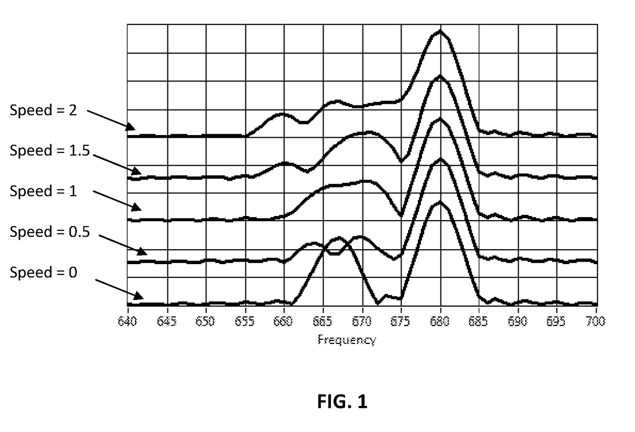
[0023]However, it is not obvious how scanning speckle error affects depth resolution, a much more concerned aspect than a length metrology aspect in OCT. In FIG. 1, simulated sweep-source OCT spectra with various beam scanning speeds are stacked over each other to illustrate the deteriorati...


PUM


Abstract

In interferometer imaging signal acquisition using a movable optical beam to sample a target with specular or non specular reflecting surfaces or internal features, beam moving during interferometer signal acquisition can generate unwanted phase error due to shifting speckle field. Examples include coherent LIDAR, Interferometry Doppler sensing and optical coherence tomography. During an interferometer signal acquisition period, an interferometer sensing beam can be substantially stationary, and active step-scanning can be synchronized with interferometer signal acquisition cycles. For interferometers using repetitive chirping lasers, passive dispersive counter-scan mechanisms can be used to assist step-scanning operation.

Description

FIELD OF THE INVENTION[0001]The present invention relates to apparatus and method of sensing beam scanning of general imaging interferometers.BACKGROUND OF THE INVENTION[0002]Various interferometer applications sense scattering field, so the interference signal comprises the coherent contribution of many scattering speckles, which in general are random in phase and magnitude. Examples include coherent LIDAR ranging, Interferometry Doppler sensing and optical coherence tomography (OCT). In these examples, a single-point or single line-of-sight sensing can be naturally extended to a higher dimensional imaging application, by incorporating lateral beam scanning such as a raster scanning pattern. In imaging applications, the beam scanning range is typically large enough to cover more than ten resolvable beam spots and more than ten interferometer measurements are made. A standard beam scanning mechanism shifts a sensing beam continuously, resulting in a continuously changing scattering ...

Claims


Application Information

Patent Timeline
Patent Type & Authority Applications(United States)
IPC IPC(8): G01B9/02G01B11/14
CPCG01B9/0203G01B9/02091G01B11/14G01B9/02002
Inventor WAN, XIAOKE
Owner WAN XIAOKE
Why Eureka
Try Eureka