Method of designing a winglet and a winglet designed thereby

a design method and winglet technology, applied in the direction of influencers by generating vortices, airflow influencers, wing shapes, etc., can solve the problems of limited maximum aircraft span and limit to the maximum feasible size of a winglet, so as to increase the total length of the winglet. , the effect of increasing the total length of the wingl

Inactive Publication Date: 2018-08-23
AIRBUS OPERATIONS LTD +1
View PDF0 Cites 0 Cited by
  • Summary
  • Abstract
  • Description
  • Claims
  • Application Information

AI Technical Summary

Benefits of technology

The patent aims to improve the effectiveness of winglets in reducing induced drag by adjusting the shape of the transition region. Specifically, it recognizes that by adjusting the curvature and location of the centre of the curvature of the transition region, the overall drag coefficient of the wingtip can be minimized. The shape of the winglet can be optimized by iteratively changing the curvature and location of the center of curvature of the transition region. The winglet design is carried out by fixing the location of the winglet tip at a maximum height and a maximum span while moving the location of the center of the curvature of the transition region outboard. This process increases the length of the winglet from root to tip, making it more effective at reducing induced drag.

Problems solved by technology

There tends to be a limit to the maximum feasible size of a winglet, especially its height, due to structural limits on the wing (for example the strength of the wing root).
The maximum aircraft span is also limited.

Method used


Image

  • Method of designing a winglet and a winglet designed thereby
  • Method of designing a winglet and a winglet designed thereby
  • Method of designing a winglet and a winglet designed thereby

Examples


Embodiment Construction

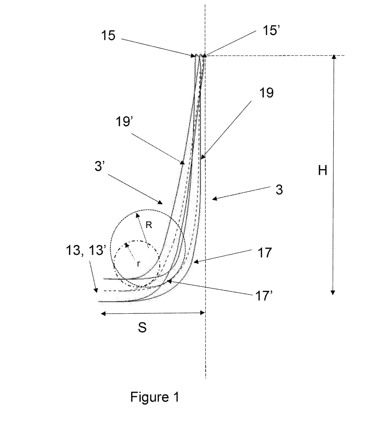
[0033]FIG. 1 shows a frontal view of an initial and a final iteration of a winglet design, created using a method according a first embodiment of the invention. The winglet 3 is for mounting on the end of the wings 5 of an aircraft 7 (the aircraft, wing and the final iteration of the winglet are shown schematically in FIG. 3).

[0034]FIG. 1 shows an initial iteration of the winglet 3′ on the left-hand side, and the final iteration of the winglet 3 on the right-hand side. Features of the initial iteration share common reference numerals with the final iteration but with the suffix ‘.

[0035]The initial shape of the winglet 3′ is determined by three criteria:

[0036]Firstly, the location of the winglet root 13′. This is the location at which the winglet is to structurally join the end of the wing 5, and also at which the shape of the winglet 3′ begins to transition away from the generally planar wing.

[0037]Secondly, the height H of the tip 15′ of the winglet 3′. This is determined by struct...


PUM


Abstract

A method of designing a winglet (3) for an aircraft (7) including: defining the location of the winglet root; defining a maximum height for the winglet tip; defining a maximum span for the winglet; creating the winglet shape by locating the winglet root (13′), locating the winglet tip (15′) at the location of maximum height and maximum span, and connecting the winglet root (13′) to the winglet tip (15′) using a winglet shape. The winglet shape includes a curved transition region (17′) extending away from the root, and a wing-like region extending from the distal end of the transition region (17′) to the winglet tip (15′). The step of creating the winglet shape includes iteratively changing the curvature and / or the location of the center of the curvature of the transition region, whilst maintaining the locations of the winglet root and winglet tip.

Description

[0001]The present disclosure relates to winglets for aircraft, to a method of designing a winglet, a method of manufacturing a winglet, and a winglet designed and / or manufactured using such methods.BACKGROUND OF THE INVENTION[0002]Winglets are well-known and can take a number of forms. Examples of winglets are shown in U.S. Pat. No. 5,348,253, U.S. Pat. No. 6,484,968, WO 2008 / 061739, WO 2008 / 155566, WO 2012 / 007358, U.S. Pat. No. 5,275,358, and WO 2012 / 171023. Generally speaking, winglets seek to reduce induced drag by increasing the effective span of the aircraft to which they are fitted.[0003]There tends to be a limit to the maximum feasible size of a winglet, especially its height, due to structural limits on the wing (for example the strength of the wing root). The maximum aircraft span is also limited. The span is effectively limited (for a given ICAO Annex 14 aerodrome code letter) by airport operating rules which govern various clearances required when manoeuvring around the a...

Claims


Application Information

Patent Timeline
IPC IPC(8): B64F5/00B64C23/06
CPCB64F5/00B64C23/069Y02T50/10B64C3/10B64C23/065
Inventor WRIGHT, CHRISTOPHERCOMMIS, BENLEOVIRIYAKIT, KASIDITHELLER, GERD
Owner AIRBUS OPERATIONS LTD
Why Eureka
Try Eureka