
Method and apparatus to determine optimal brain stimulation to induce desired behavior

a brain stimulation and optimal technology, applied in the field of system for inducing a desired behavior, can solve the problems of slow and needing to be restarted, requires tedious tuning of annealing parameters, and no prior art methods exist to produce any desired behavioral

Active Publication Date: 2018-08-23
HRL LAB
View PDF1 Cites 4 Cited by
  • Summary
  • Abstract
  • Description
  • Claims
  • Application Information

AI Technical Summary

Benefits of technology

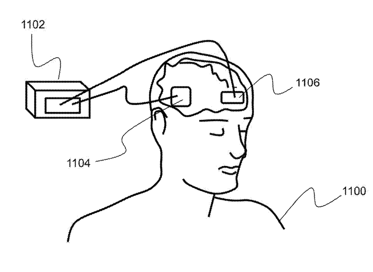
The present invention relates to a system for inducing a desired behavior using brain stimulation. The system includes a brain monitoring subsystem for sensing brain activity and a brain stimulation subsystem for applying electrical current stimulation. The system also includes one or more processors and a computer-readable medium with executable instructions that perform multiple operations. The system uses a graphical representation to identify a specific behavior and map it to a sub-graph, which is then translated into a set of concept features. The system then determines the appropriate electrical current stimulation to produce the desired behavior and causes it to be applied via the stimulation subsystem. The present invention provides a tool for inducing desired behavior and has applications in brain research and brain-computer interface technology.

Problems solved by technology

The state-of-the-art to discover invasive and non-invasive stimulation patterns to enhance a particular behavioral function is essentially based on an expensive experimental process of trial and error.
Simulated annealing, which is state-of-the-art for hard optimization problems with many local minima, requires tedious tuning of annealing parameters.
It is slow and must be restarted from scratch when the optimization target moves.
No prior art methods exist to produce any desired behavioral effect.

Method used


Image

  • Method and apparatus to determine optimal brain stimulation to induce desired behavior
  • Method and apparatus to determine optimal brain stimulation to induce desired behavior
  • Method and apparatus to determine optimal brain stimulation to induce desired behavior

Examples


Embodiment Construction

[0029]The present invention relates to a system for inducing a desired behavior and, more particularly, to a system for inducing a desired behavior using a determined brain stimulation.

[0030]The following description is presented to enable one of ordinary skill in the art to make and use the invention and to incorporate it in the context of particular applications. Various modifications, as well as a variety of uses in different applications will be readily apparent to those skilled in the art, and the general principles defined herein may be applied to a wide range of aspects. Thus, the present invention is not intended to be limited to the aspects presented, but is to be accorded the widest scope consistent with the principles and novel features disclosed herein.

[0031]In the following detailed description, numerous specific details are set forth in order to provide a more thorough understanding of the present invention. However, it will be apparent to one skilled in the art that t...


PUM


Abstract

Described is a system for inducing a desired behavioral effect using an electrical current stimulation. A brain monitoring subsystem includes monitoring electrodes for sensing brain activity, and a brain stimulation subsystem includes stimulating electrodes for applying an electrical current stimulation. Multi-scale distributed data is registered into a graphical representation. The system identifies a sub-graph in the graphical representation and maps the sub-graph onto concept features, generating a concept lattice which relates the concept features to a behavioral effect. Finally, an electrical current stimulation to be applied to produce the behavioral effect is determined.

Description

CROSS-REFERENCE TO RELATED APPLICATIONS[0001]This is a Continuation-in-Part Application of U.S. Non-Provisional application Ser. No. 14,747,407, filed on Jun. 23, 2015, entitled, “System and Method for Determining a Plurality of States to Assign to Each of a Plurality of Actors,” which is a Non-Provisional Application of U.S. Provisional Patent Application No. 62 / 015,871, filed on Jun. 23, 2014, entitled, “System and Method for Determining a Plurality of States to Assign to Each of a Plurality of Actors,” the entirety of which are incorporated herein by reference.[0002]This is also a Non-Provisional Application of U.S. Provisional Application No. 62 / 500,500, filed on May 3, 2017, entitled, “Method and Apparatus to Determine Optimal Brain Stimulation to Induce Desired Behavior,” the entirety of which is incorporated herein by reference.BACKGROUND OF INVENTION(1) Field of Invention[0003]The present invention relates to a system for inducing a desired behavior and, more particularly, t...

Claims


Application Information

Patent Timeline
IPC IPC(8): A61N1/36A61B5/0478A61N1/02A61N1/04A61B5/00A61B5/04A61B5/16A61B5/0484
CPCA61N1/36025A61B5/0478A61N1/025A61N1/0456A61N1/36031A61B5/743A61B5/04012A61B5/16A61B5/0484A61N1/0529A61N1/36017A61N1/36082A61B5/24A61B5/316A61B5/377A61B5/291
Inventor PILLY, PRAVEEN K.HOWARD, MICHAEL D.HOFFMANN, HEIKOLU, TSAI-CHINGNI, KANG-YUPAYTON, DAVID W.
Owner HRL LAB
Learn More